
Special Articles on 3GPP Release 18 Standardization Activities (1)
5G-Advanced Radio Technologies in 3GPP Release 18
5G-Advanced NR RAN
Shinya Kumagai
6G Network Innovation Department
Daiki Takeda
Device-Tech Development Department
Kei Ando, Hidekazu Shimodaira, Tianyang Min and Shoki Inoue
Radio Access Network Technology Promotion Office
Abstract
At 3GPP, following the drafting of new radio access technology called NR toward 5G as Release 15 specifications, Release 16/17 specifications were drafted as extensions to that technology. 5G specifications from Release 18 onwards are defined as 5G-Advanced specifying further technical extensions to 5G. With this positioning in mind, the drafting of Release 18 specifications that began in March 2022 was completed in June 2024. This article presents an overview of 5G-Advanced radio technologies in Release 18.
01. Introduction
-
After the drafting of specifications for New Radio...
Open

After the drafting of specifications for New Radio (NR)*1, a new radio access technology for the 5th Generation mobile communications system (5G), as 3rd Generation Partnership Project (3GPP) Release 15 (Rel-15), Rel-16/17 specified advanced technologies for enhanced Mobile BroadBand (eMBB)*2 and Ultra-Reliable and Low Latency Communication (URLLC)*3 as well as technical extensions for creating a new business field called Industrial Internet of Things (IIoT)*4 to promote IoT in industry. Additionally, to support new scenarios and use cases, Rel-17 provided support for even higher frequency bands and for Non-Terrestrial Network (NTN)*5 systems and added a low-cost NR device category called Reduced Capability (RedCap)*6 toward wearable terminals and other devices.
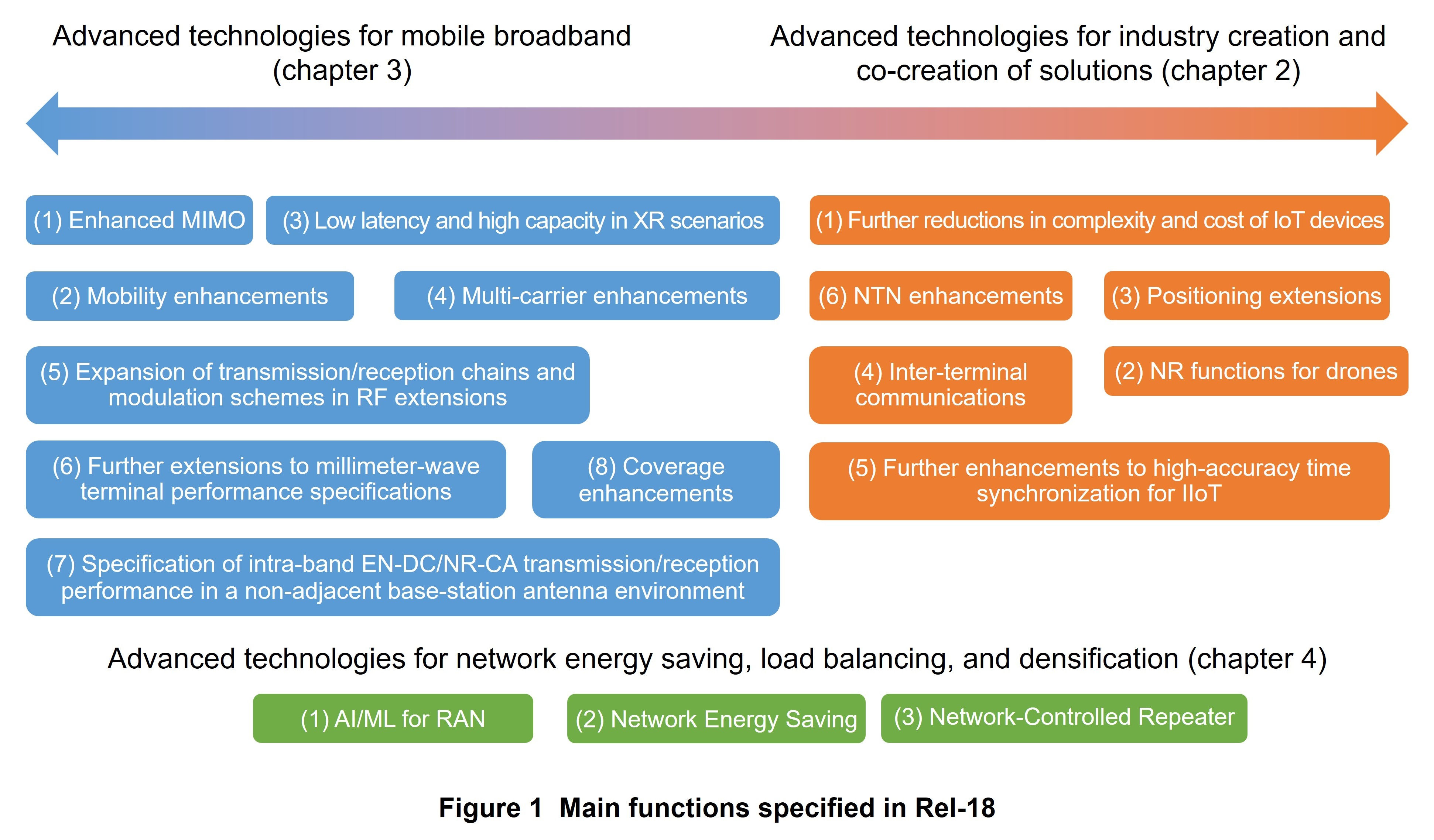
At 3GPP, Rel-18 and later specifications are defined as 5G-Advanced, and in addition to adding functions targeted for commercialization in the latter half of the 2020s, they are positioned as a step toward the 6th Generation mobile communications system (6G) through study and work items that take a balanced approach from the viewpoints of (1) mobile-broadband evolution and 5G expansion into various industries, (2) technologies that meet short-term needs and technologies that meet medium- to long-term needs, and (3) device and network evolution. In this way, Rel-18 aims to contribute to the provision of new value by 5G. Main functions specified in Rel-18 are summarized in Figure 1. This article presents an overview of main technical extensions specified in Rel-18 and provides some background to those specifications.
- NR: Radio system standard formulated for 5G. Compared with 4G, NR enables high data rate communications using high frequency bands (e.g. sub-6 GHz bands and 28 GHz band) and low-latency and high-reliability communications for achieving advanced IoT.
- eMBB: Generic name for communications requiring high data rates and large capacity.
- URLLC: Generic name for communications requiring low latency and high reliability.
- IIoT: IoT for industrial fields such as network connections for equipment and devices in a factory and elsewhere.
- NTN: A network that extends the communications area to diverse locations including the air, sea, and space using non-terrestrial media such as satellites and high-altitude platform stations without limiting the coverage area to land.
- RedCap: The name of a simple UE category introduced in Rel-17 NR that reduces device complexity by decreasing the number of transmit/receive antennas and bandwidth mandatorily supported in NR UEs.
-
2.1 Further Reductions in Complexity and Cost of IoT Devices
Open
In Rel-17, RedCap was specified as NR-optimized terminals for middle-range IoT services positioned between high-end IoT terminals to support NR functions such as eMBB and URLLC and low-end IoT terminals provided by enhanced Machine Type Communication (eMTC)*7 and Narrow Band-IoT (NB-IoT)*8. However, Rel-17 RedCap transmits/receives data in a 20 MHz bandwidth wider than that of low-end IoT terminals, and after it was pointed out that there was still room for reducing terminal complexity, discussions were held on functional extensions for making RedCap applicable to areas closer to low-end IoT.
In Rel-18, enhanced Reduced Capability (eRedCap) terminals were specified with the aim of extending supported use cases to an area called the smart grid*9 by further reducing terminal complexity (data channel bandwidth, peak data rate) compared with RedCap.
2.2 NR Functions for Drones
For LTE drones introduced in Rel-15, altitude reports, flightpath reports, and a function for suppressing excessive measurement reporting were specified. Then, for NR drones first introduced in Rel-18, functional extensions were made in addition to incorporating the basic functions of LTE drones. Specifically, a new event taking drone altitude information into account was introduced as a trigger for making a measurement report. Additionally, in the setting of measurement reports, specifications enabled the beams to be measured by the drone to be set according to altitude, and in drone flightpath reports, they enabled flightpath information to be updated. Also introduced was a Broadcasting Uncrewed Aerial Vehicle ID (BRID) function for broadcasting a drone ID by a sidelink*10 so that a regulatory authority could identify a drone flight and a Detect And Avoid (DAA) broadcast function for preventing collisions between drones.
2.3 Functional Extensions to Positioning Technology in NR
In NR, positioning functions for estimating User Equipment (UE)*11 position have been introduced in NR since Rel-16. A variety of NR positioning technologies have been specified that go beyond relatively simple positioning methods using, for example, Cell ID*12 and Timing Advance (TA)*13 to include high-accuracy positioning methods using signal propagation time and direction of arrival, etc. as well as functional extensions to improve accuracy in the horizontal/vertical directions and reduce latency to support industrial needs having stricter requirements.
In Rel-18, specifications were drafted as further functional extensions in the following two directions to improve positioning accuracy, reduce latency, and reduce terminal power consumption.
- Support new positioning methods and extensions to existing positioning technologies with the aim of achieving positioning accuracy on the cm level
- Expand the application areas of NR positioning technologies through functional extensions envisioning simple NR terminals (RedCap) and Vehicle to Everything (V2X)*14 use cases
2.4 Inter-terminal Communications (Sidelink)
At 3GPP, Rel-16 specified basic 5G sidelink functions for V2X while Rel-17 added a function for reducing power consumption and a function for achieving high reliability and low-latency in 5G sidelink targeting pedestrian terminals and public-safety terminals in V2X. On the other hand, there are still many problems in achieving IoT networks using sidelink, and as a result, they have yet to be widely deployed throughout the world.
To therefore achieve diverse industrial-collaboration solutions in 5G, Rel-18 made further functional enhancements to sidelink communications. Specifically, Rel-18 added a function for the 5-6 GHz unlicensed spectrum*15 with the aim of improving the data rate and expanding the application area, a sidelink carrier aggregation function with the aim of achieving efficient V2X services, and a function for coexistence with LTE sidelink.
2.5 Further Enhancements to High-accuracy Time Synchronization for IIoT
In Rel-16/17, a high-accuracy time synchronization function was specified for IIoT, and in Rel-18, a function for monitoring and reporting the status of time synchronization was introduced to deal with changes in synchronization accuracy. For example, this function enables countermeasures to be taken when synchronization accuracy deteriorates such as by having the UE temporarily suspend service to prevent errors from occurring. In this function, the Access and Mobility management Function (AMF)*16 provides the gNB*17 with control information related to synchronization quality for each user, and based on this control information, the gNB reports the status of time synchronization to UE. Additionally, if there should be an update in this status, a “change has occurred” announcement is made so that the UE can deal with a change in synchronization quality regardless of its communication state.
2.6 NTN Enhancements
Envisioning the use of satellites in GeoStationary Orbit (GSO) and Non GSO (NGSO), Rel-17 specified NTN on the premise of UEs equipped with a Global Navigation Satellite System (GNSS)*18 function. Then, with the aim of achieving a more practical and efficient NTN, Rel-18 specified functional enhancements including “UpLink (UL) coverage improvements” to support small-form terminals like smartphones, “validation of terminal position” to avoid relying solely on the GNSS function for position information, “NTN-TN and NTN-NTN mobility functional extensions” to bolster service continuity considering the large propagation delay unique to NTN and satellite movement, and “frequency band support for Very Small Aperture Terminal (VSAT)*19” in scenarios using frequency bands above 10 GHz.
- eMTC: An LTE communications specification for low data rate communications for IoT devices (sensors, etc.) using a narrow bandwidth.
- NB-IoT: An LTE communications specification for low data rate communications for IoT devices (sensors, etc.) using a narrower bandwidth than eMTC.
- Smart grid: A power distribution network that incorporates radio sensors in the power system to autonomously monitor, control, and optimize the supply side and demand side in real time.
- Sidelink: A communication link for communications between UEs without passing through a base station.
- UE: A mobile device having functions conforming to 3GPP.
- Cell ID: Identifying information assigned to each cell.
- TA: The amount of timing adjustment on the UE side to maintain signal orthogonality between multiple UEs.
- V2X: A generic name for Vehicle-to-Vehicle (V2V) direct communications between cars, Vehicle-to-Infrastructure (V2I) direct communications between a car and roadside devices (radio communications equipment installed along a road), Vehicle-to-Pedestrian (V2P) direct communications between vehicles and pedestrians, and Vehicle-to-Network (V2N) wide-area communications via base stations in a cellular network such as LTE or 5G.
- Unlicensed spectrum: A frequency band usable without the need for an official license and not limited to a particular telecommunications operator.
- AMF: Equipment in the 5G Core (5GC) that serves the UE in a particular area.
- gNB: Node providing NR user plane and control plane protocol terminations towards the UE, connected via the NG interface to the 5G Core Network (5GC).
- GNSS: Generic name for satellite positioning systems such as Global Positioning System (GPS) and Quasi-Zenith Satellite System (QZSS).
- VSAT: Equipment able to communicate with aircraft using a compact parabolic antenna. It is large relative to a smartphone, and is expected to be connected to equipment such as a wired hub, fixed-line telephone, or PC.
-
3.1 Enhanced MIMO
Open
1) Extension to Maximum Number of Layers in MU-MIMO
For the DownLink (DL), Rel-15 drafted specifications to enable a maximum of 8 layers*20 for Single User-MIMO (SU-MIMO)*21 and a maximum of 12 layers for Multi User-Multiple Input Multiple Output (MU-MIMO)*22. In Rel-18, discussions were held on extending the maximum number of layers for MU-MIMO to 24 layers to increase capacity even further. Here, the number of ports of the DeModulation Reference Signal (DMRS)*23 for the UL/DL physical data channels determines the maximum number of layers. The Frequency Domain Orthogonal Cover Code (FD-OCC)*24 of length 2 (consisting of two values) used by Rel-15 DMRS was extended to a FD-OCC of length 4 thereby doubling the maximum number of DMRS ports.
2) UL Transmission in a Multi-TRP Scenario
In Rel-16 and Rel-17, specifications were drafted to enable a base station to use two instances of a Transmission and Reception Point (TRP)*25 at different locations to apply a multi-TRP scenario for transmitting/receiving signals to the DL. This effectively increases the number of MIMO*26 layers, which provides a DL throughput improvement effect and reliability improvement effect through retransmission.
In Rel-18, with the aim of improving the effective throughput and reliability in the UL in a multi-TRP scenario the same as in the DL, a function was specified to enable UE to use two UL transmission beams simultaneously via two transmission panels to transmit physical data and control channels in the UL.
3) Extension to Number of UL Transmission Layers
A maximum of four transmission layers in the UL was specified in Rel-15. This was extended to a maximum of eight transmission layers in the UL in Rel-18 to improve throughput. Specifically, the codebook*27 that provides UL precoder*28 information was extended to a maximum of eight layers and the Sounding Reference Signal (SRS)*29 was extended to a maximum of eight ports.
4) Extended Type-II Codebook
In Rel-15, two types of Channel State Information (CSI)*30 codebooks reported by UE to the base station were specified as Type-I and Type-II. The problem here, however, was that precoder information reported by the Type-II codebook was greatly affected by the Doppler frequency*31 caused by UE movement or other factors compared with that reported by the Type-I codebook. In response to this problem, Rel-18 specified an extended Type-II codebook that enables UE to measure and report the predicted values of precoder temporal variation.
3.2 Mobility Enhancements
A conventional handover*32 is performed on the Radio Resource Control (RRC)*33 layer of the protocol stack, which is referred to as Layer 3 (L3)*34 mobility. To decrease interruption time in such conventional handovers, Rel-18 specifies that handovers are to be performed on an even lower layer (L1/L2*35) referred to as Lower layer Triggered Mobility (LTM).
In LTM, the handover-source base station sets information on handover candidate cells*36 in the UE beforehand based on the conventional L3 quality measurement report. Then, just before handover execution, the handover-source base station selects the optimal target cell and beam from among the handover candidate cells based on an L1 measurement report from UE and sends a handover instruction to UE by L2 signaling*37 called a LTM cell switch command.
Additionally, for LTM within the same Distributed Unit (DU)*38, a handover can be made without performing an L2 reset (Packet Data Convergence Protocol (PDCP)*39 reestablishment, Radio Link Control (RLC)*40 reestablishment) thereby reducing interruption time.
Furthermore, in a conventional handover, a Random Access CHannel (RACH)*41 procedure was essential for the UE to perform UL synchronization with the target cell, but in LTM, an Early TA function was introduced to reduce RACH delay. Specifically, a handover that eliminates the need for a RACH procedure at the time of LTM execution is made possible by having UE perform UL synchronization with the target cell before LTM execution.
Moreover, since LTM makes it possible to specify an UL/DL Transmission Configuration Indicator (TCI) state ID*42 with the cell switching command and to directly synchronize with a beam of the target cell, beam-level high-speed mobility becomes possible.
We note here that Rel-18 LTM targets only intra-Central Unit (CU) LTM*43 and that the plan is to specify inter-CU LTM*44 in Rel-19.
3.3 Low Latency and High Capacity in XR Scenarios
Extended Reality (XR)*45 is positioned as important use cases and services in future mobile networks. However, XR requires both a high data rate to transmit high-definition video and low latency to reflect user actions in real time without creating an uneasy feeling. In addition, envisioning the use of small and lightweight terminals such as wearable devices, there will be limitations in a terminal's battery capacity.
In response to such high-performance and low-power-consumption requirements, Rel-18 specified “XR Awareness” for transmitting UL data more effectively by adding XR-specific assistance information such as extended Buffer Status Report (BSR)*46 information and latency information, “XR capacity improvements” for improving communications capacity per cell by improving resource usage efficiency when making Configured Grant*47 settings and by grouping and controlling multiple instances of a PDCP Protocol Data Unit (PDU)*48, and “low power consumption for XR terminals” specific to XR use cases such as receive-period extension in Discontinuous Reception (DRX)*49 and a UL transmission method when making Configured Grant settings.
3.4 Multi-carrier Enhancements
From Rel-15 and beyond, the 5G network continued to expand, but from here on, it is thought that cutbacks in the operation of the 3rd Generation mobile communications system (3G) and 4th Generation mobile communications system (4G) will increase the opportunities for diverting the Frequency Range 1 (FR1)*50 band traditionally used by 3G/4G to 5G. However, since the frequency bands that come to be used by 5G in this way are often fragmented and narrow, there is a need for multicarrier operation that bundles together multiple bands. On the other hand, considering that sufficient bandwidth can be secured within the same band in the case of the FR2*51 band (or parts of the FR1 band), multicarrier operation bundled within the same band can also be effective.
To make multicarrier operation as described above more efficient, Rel-18 specified a function for scheduling the Physical Downlink Control CHannel (PDCCH)*52 of one cell for multiple cells and a function called UL Tx switching for dynamically switching the transmission band from among a maximum of four bands.
3.5 Expansion of Transmission/Reception Chains and Modulation Schemes in RF Extensions
From Rel-15 on, throughput performance has continued to improve due to expansion of UE transmission/reception chains. In Rel-18, the following expansions in UE transmission/reception chains were specified.
1) FR1
In FR1, extensions were made to a maximum of four UL chains (four chains for single carrier transmission and three chains for a combination of two bands) up to a maximum transmission power of 29 dBm and to a maximum of eight DL chains (including 8-layer DL MIMO) for Fixed Wireless Access (FWA)*53 terminals, Customer Premises Equipment (CPE)*54 terminals, vehicle-mounted terminals, and industrial devices whose deployment constraints are relatively few compared with handheld UE*55 such as smartphones. Additionally, for handheld UE like smartphones, a specification was introduced to support up to a maximum of four DL chains in frequency bands less than 1 GHz.
Furthermore, for simultaneous transmission and reception in carrier aggregation*56 and dual connectivity*57, techniques combined with UE capability*58 were specified for mitigation measures against reception sensitivity degradation caused by the coupling*59 of a terminal's own transmission signal within that terminal. This makes it possible for the network side to identify terminals that support techniques for mitigating reception sensitivity degradation, which means that more appropriate scheduling control is expected.
2) FR2
In FR2, π/2 Binary Phase Shift Keying (π/2 BPSK)*60, Quadrature Phase Shift Keying (QPSK)*61, 16 Quadrature Amplitude Modulation (16QAM)*62, and 64QAM*63 have conventionally been supported, but Rel-18 newly specified 256QAM*64 that transmits 8 bits per symbol*65. This makes it possible to transmit 8/6 times the amount of information at one time compared with 64QAM that transmits 6 bits per symbol.
3.6 Further Extensions to Millimeter-wave UE Performance Specifications
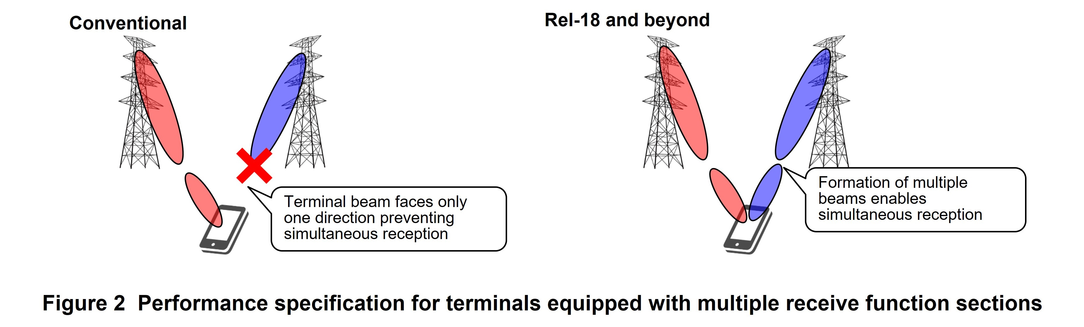
The conventional requirement that had to be satisfied by UE within the same FR2 frequency band is the capability of forming one beam by one antenna panel. However, since the requirement for DL MIMO of FR2 was a maximum of 2 layers per beam, performing four-layer reception as commonly used in FR1 required the use of two different beams in FR2.
To improve DL throughput in FR2, Rel-18 specified the UE performance requirements that enables four-layer DL MIMO in the same FR2 frequency band by simultaneously forming two beams assuming that the UE is equipped with two instances of an antenna panel connected to a signal processing unit (Figure 2).
Additionally, in FR2, there is the requirement of UE beam sweeping*66 when performing radio quality measurements, so the time needed for performing these measurements is long compared with FR1. In Rel-18, the time needed for beam sweeping can be reduced by equipping the UE with multiple receiving units each of which can perform beam sweeping independently, and since it becomes possible here to partially relax restrictions that prevent data reception during radio quality measurements, DL throughput in FR2 can be expected to improve.
3.7 Specification of Intra-band EN-DC/NR-CA Transmission/Reception Performance in a Non-adjacent Base-station Antenna Environment
Since LTE band 42 (3.4-3.6 GHz) and NR bands n77 (3.3-4.2 GHz) and n78 (3.3-3.8 GHz) are overlapping frequency bands, they have been handled as intra-band under the assumption that base-station antennas are deployed physically adjacent to each other. For this reason, received signal power difference and signal transmission/reception time difference in Evolved Universal Terrestrial Radio Access Network New Radio Dual Connectivity (EN-DC)*67 /NR-Carrier Aggregation (NR-CA)*68 did not take into account propagation path differences. In actuality, however, due to differences in license issuance dates, LTE band refarming to NR, and other factors, there were cases in which base-station antennas for these bands were deployed in physically separated locations, which presented a problem in that specifications for the power differences and time differences described above could not be satisfied and normal EN-DC/NR-CA operation in those bands could not be guaranteed. In Rel-16 and Rel-17, in which the number of layers in EN-DC were limited to two for each band for a maximum of four layers, the application range of these specifications were expanded allowing the received signal power difference to be as much as 25 dB from what had been 6 dB and the signal transmission/reception time difference to be lengthened by 30 μs. In Rel-18, these specifications were extended for application to NR-CA.
3.8 Coverage Enhancements
1) Physical Random Access Channel (PRACH)*69 repetitions
In Rel-17, repetition extensions were specified for the Physical Uplink Shared CHannel (PUSCH)*70 and the Physical Uplink Control CHannel (PUCCH)*71 for the purpose of extending coverage*72. However, it was pointed out that PRACH coverage could cause a bottleneck in overall cell coverage in cells slated for implementation of the Rel-17 coverage enhancement function. To solve this problem, PRACH repetition was specified in Rel-18.
2) CP-OFDM/DFT-S-OFDM switching by indication on the physical layer
In Rel-15, Cyclic Prefix-Orthogonal Frequency Division Multiplexing (CP-OFDM)*73 and Discrete Fourier Transform-Spread-OFDM (DFT-S-OFDM)*74 were specified as two types of waveforms for PUSCH transmissions. CP-OFDM is superior in terms of flexibility in resource allocation in the frequency direction while DFT-S-OFDM is superior from a coverage viewpoint due to a low Peak to Average Power Ratio (PAPR)*75 of the generated signal. In Rel-15, switching between these waveforms could only be performed by configuration in upper layers*76, but Rel-18 specifications enabled switching by indication on the physical layer*77, which means control with finer temporal granularity thereby improving throughput and making it easy to secure coverage.
- Layers: In MIMO, each layer corresponds to a stream—multiple streams may be simultaneously transmitted.
- SU-MIMO: Technology for performing MIMO communications using multiple transmit/receive antennas of a single user.
- MU-MIMO: Technology for performing MIMO communications using the receive antennas of multiple users. Dividing spatial streams among users enables user multiplexing.
- DMRS: A reference signal used for channel estimation, used for decoding data transmitted on the UL and DL.
- FD-OCC: Application of an orthogonal code to resources in the frequency domain.
- TRP: A set of one or more transmitter/receiver antenna ports installed at a single location in a base station. A base station configuration that uses only one transmitter/receiver antenna port at a single location is called a single TRP, while a base station configuration that uses multiple transmitter/receiver antenna ports at multiple locations is called multi-TRP.
- MIMO: A signaling technique whereby multiple transmit and receive antennas are used to transmit signals simultaneously and at the same frequency to improve communication quality and the efficiency of frequency utilization.
- Codebook: A set of predetermined precoding weight matrix candidates.
- Precoder: Coefficients multiplied before transmission with respect to a certain digital signal.
- SRS: A reference signal used to measure UL channel quality, reception timing, etc. at the base station.
- CSI: Information describing the state of the radio channel traversed by the received signal.
- Doppler frequency: Error in frequency caused by the movement of the transmitter or receiver in wireless communications.
- Handover: Switching to a cell as a connection destination by UE.
- RRC: A protocol for controlling radio resources in a radio network.
- L3: The third layer (the network layer) in the Open Systems Interconnection (OSI) reference model.
- L1/L2: Layers in the OSI reference model. Layer 1 is the physical layer and Layer 2 is the data link layer.
- Cells: A cell is the smallest area unit for sending and receiving radio signals between mobile communications network and mobile terminals.
- Signaling: Control signals used for communications between terminals and base stations.
- DU: A distributed node when dividing a 5G base station into a centralized node and distributed node.
- PDCP: A sublayer of Layer 2 and protocol that performs encryption, integrity checks, reordering, header compression, etc.
- RLC: A protocol for controlling retransmission and other functions as a sublayer of Layer 2.
- RACH: A physical channel used by mobile terminals to initially transmit a signal to the base station in the random-access procedure.
- TCI state ID: Identifier of information related to signal/channel Quasi-Co-Location (QCL).
- Intra-CU LTM: Handover performed between two cells within the same base station.
- Inter-CU LTM: Handover performed between two cells between different base stations.
- XR: Generic name for technology that provides new experiences by merging real space and virtual space using wearable terminals, etc.
- BSR: A type of signal-control Medium Access Control Control Element (MAC CE) sent by the UL on the MAC sublayer. It is used by UE to report the amount of buffered UL data that it would like to send to the gNB. In addition, MAC is a sublayer in Layer 3 of the radio interface—it refers to protocol for allocating radio resources, performing data mapping on the Transport Block (TB), controlling Hybrid Automatic Repeat Request (HARQ) retransmission, etc.
- Configured Grant: A mechanism for allocating PUSCH resources beforehand from the base station on a user-by-user basis so that UE can transmit PUSCH by those resources if UL data is generated without having to transmit a Scheduling Request (SR).
- PDU: A unit of data processed by a protocol layer/sublayer.
- DRX: Intermittent reception control used to reduce UE power consumption.
- FR1: A frequency range of 410-7,125 MHz.
- FR2: A frequency range of 24,250-71,000 MHz.
- PDCCH: Control channel for the physical layer in the DL.
- FWA: Refers to a fixed wireless access system as one type of wireless communications standard. In contrast to a portable terminal like a smartphone, an FWA terminal is used in a fixed manner, which means that it is generally easy in FWA to deploy various types of wireless signal processing hardware with a device volume larger than that of portable terminals.
- CPE: Refers to a wireless system installed on customer premises as one type of wireless communications standard. With CPE, it is generally easy to deploy various types of wireless signal processing hardware with a device volume larger than that of portable terminals.
- Handheld UE: A device that the user holds in one's hands during use such as the so-called smartphone.
- CA: A technology that achieves higher transmission speeds by simultaneously transmitting and receiving data using multiple carriers supported by a single base station.
- Dual Connectivity: A technology that achieves wider bandwidths by having a terminal connect to two base stations and transmit and receive data with each base station simultaneously.
- UE capability: Generic term for the functionality supported by a terminal, such as which of the various functions specified in standards and which of the performance requirements accompanying those functions are supported, or which of multiple settings that can be taken when using a function are supported.
- Coupling: A phenomenon that occurs when signals transmitted from a transmit antenna on radio equipment are received by a receive antenna on the same equipment.
- π/2 BPSK: In the BPSK digital modulation scheme in which two values of information correspond to two phase states, a modulation scheme that avoids sudden phase changes by shifting the reference phase state for each modulation by π/2 (90 degrees) resulting in a lower peak-to-average power ratio.
- QPSK: A digital modulation scheme that allows transmission of 2 bits of information at the same time by assigning one value to each of four phases.
- 16QAM: A digital modulation scheme that allows transmission of 4 bits of information simultaneously by assigning one value to each of 16 different combinations of amplitude and phase.
- 64QAM: A digital modulation scheme that allows transmission of 6 bits of information simultaneously by assigning one value to each of 64 different combinations of amplitude and phase.
- 256QAM: A type of modulation scheme. 256QAM modulates data bits through 256 different amplitude and phase signal points. A single modulation can transmit 8 bits of data.
- Symbol: A time unit of transmitted data consisting of multiple subcarriers in the case of OFDM. Multiple bits are mapped to each subcarrier (e.g., 2 bits in QPSK).
- Beam sweeping: When using multiple beams, the spatial sweeping of those beams by switching from one to another continuously.
- EN-DC: An architecture for NR non-standalone operation. Performs RRC connections with LTE wireless and uses NR as an additional wireless resource.
- NR-CA: A technology that achieves higher transmission speeds through band expansion by simultaneously transmitting and receiving data using multiple NR carriers while maintaining backward compatibility.
- PRACH: Physical channel for transmission when the UE establishes a connection with a cell, for example, for initial access or handover.
- PUSCH: Shared channel used for transmitting data on the UL.
- PUCCH: Physical channel used for transmitting control signals on the UL.
- Coverage: The area (cell radius) in which communications with UEs per base station can be carried out. The greater the coverage, the fewer the number of base stations to be installed.
- CP-OFDM: A waveform generation method that adds the processing called CP—inserting a copy of the trailing part of the signal to the head of the signal—for time-domain signals generated by an Inverse Fast Fourier Transform (IFFT).
- DFT-S-OFDM: A waveform generation method that applies DFT to a signal when generating frequency-domain signals before CP-OFDM processing.
- PAPR: Ratio of peak power to average power over time of a signal generated at any time.
- Upper layers: All layers positioned above the physical layer such as MAC, PDCP, RLC, S1 Adaptation Protocol (S1AP), and X2AP.
- Physical layer: First layer of the Open Systems Interconnection (OSI) reference model; for example, “physical-layer specification” expresses the wireless interface specification concerning bit propagation.
-
4.1 AI/ML for RAN
Open
In Rel-18, Artificial Intelligence/Machine Learning (AI/ML)*78 functions were specified to achieve the three use cases of Mobility Optimization, Load Balancing*79, and Network Energy Saving.
- In Mobility Optimization, it is now possible to include the UE's trajectory predicted by AI/ML in the handover request message sent by the handover-source base station to the handover-destination base station, which can then use that information to select an appropriate handover destination at the time of the next handover.
- In Load Balancing, it is now possible to exchange future load conditions of adjacent gNBs predicted by AI/ML (e.g., the number of future active UEs) between gNBs and to use that information to perform look-ahead load-balancing control and smarter resource control.
- In Network Energy Saving, Rel-18 specifications newly defined Energy Cost as a metric*80 for measuring gNB energy consumption and made it possible to exchange the Energy Cost of adjacent gNBs predicted by AI/ML between gNBs. It is expected that this information combined with the above information on future gNB load conditions predicted by AI/ML will be able to optimize overall network energy consumption through load-balancing control. We note here that AI/ML algorithms and models are outside the 3GPP scope.
4.2 Network Energy Saving
Saving energy on the network side has become a major issue for mobile network operators due to recent social demands arising from a greater awareness of environmental problems and to an increase in the number of antennas, wider bandwidths, and more frequency bands accompanying advances in wireless networks. Network Energy Saving (NES) was specified for the first time in Rel-18 as energy saving technology on the network side. Rel-18 NES consists of energy saving technologies in the spatial, power, frequency, and time domains as well as extensions to existing UE access control and Conditional HandOver (CHO)*81 to enable smooth operations when actually applying these technologies to a network. These measures make it possible to provide a network that enhances energy-savings effects on the network side and curtails operating costs while taking the environment into account.
4.3 Network-Controlled Repeater
A new NR node*82 was specified for further developing the 5G area and expanding coverage, and in Rel-17, specifications for an NR repeater were drafted. This NR repeater follows in the footsteps of repeaters up to 4G by amplifying and forwarding signals transmitted and received between the base station and UE. However, only simple amplification and forwarding were specified for the operation of the NR repeater and constraints were placed on repeater operations and functions, so in Rel-18, a new repeater format called Network-Controlled Repeater (NCR) was specified to enable the network to partially control repeater operation. This specification makes it possible to perform repeater beam control and to operate the repeater in higher frequency bands, which should lead to further extensions and densification of the NR network.
- AI/ML: Makes inferences using a model, or generates models for making inferences using ML.
- Load balancing: The process of distributing traffic load among cells.
- Metric: Refers to the measurement or quantification of a target attribute or state based on a certain standard.
- CHO: One method for implementing a handover in which the network side notifies UE of the switching destination and switching conditions beforehand instead of issuing instructions at actual handover time.
- Node: A network point that propagates a value received from input.
-
This article provided an overview of 5G-Advanced radio ...
Open
This article provided an overview of 5G-Advanced radio technologies in 3GPP Rel-18 specifications. Please refer to other articles in this issue for details on advanced technologies for industry creation and co-creation of solutions, advanced technologies for mobile broadband, and advanced technologies for the radio network introduced in this article [1]-[3]. At 3GPP, the drafting of Rel-19 specifications as the second set of 5G-Advanced specifications began in December 2023 [4]. NTT DOCOMO strongly supports 5G standardization at 3GPP and will contribute to the further development of 5G standards going forward.
-
REFERENCES
Open
- [1] S. Yoshioka et al.: “Advanced Technologies for Industry Creation and Solution Co-creation in 3GPP Release 18,” NTT DOCOMO Technical Journal, Vol. 26, No. 2, Oct. 2024.
https://www.docomo.ne.jp/english/corporate/technology/rd/technical_journal/bn/vol26_2/003.html - [2] Y. Matsumura et al.: “Enhanced Mobile Broadband Technologies in 3GPP Release 18,” NTT DOCOMO Technical Journal, Vol. 26, No. 2, Oct. 2024.
https://www.docomo.ne.jp/english/corporate/technology/rd/technical_journal/bn/vol26_2/004.html - [3] D. Kurita et al.: “Advanced Technologies for Network Energy Saving, Load Balancing, and High Densification in 3GPP Release 18,” NTT DOCOMO Technical Journal, Vol. 26, No. 2, Oct. 2024.
https://www.docomo.ne.jp/english/corporate/technology/rd/technical_journal/bn/vol26_2/005.html - [4] H. Harada et al.: “5G-Advanced Standardization Trends,” NTT DOCOMO Technical Journal, Vol. 26, No. 2, Oct. 2024.
https://www.docomo.ne.jp/english/corporate/technology/rd/technical_journal/bn/vol26_2/001.html
- [1] S. Yoshioka et al.: “Advanced Technologies for Industry Creation and Solution Co-creation in 3GPP Release 18,” NTT DOCOMO Technical Journal, Vol. 26, No. 2, Oct. 2024.

