
Special Articles on 3GPP Release 18 Standardization Activities (1)
Advanced Technologies for Network Energy Saving, Load Balancing, and High Densification in 3GPP Release 18
5G NR AI/ML for NG-RAN NES
Daisuke Kurita and Taichi Sichijo
6G Network Innovation Department
Shoki Inoue and Mio Nakamura
Radio Access Network Technology Promotion Office
Abstract
3GPP Rel-16/17 introduced technologies for increasing data rate and capacity in the mobile communications network and Rel-18 made further extensions. Rel-18 also introduced advanced technologies having a different approach compared with existing technologies to provide new value to the 5G network. This article describes specifications for these newly introduced technologies in 3GPP Rel-18 toward an advanced wireless network.
01. Introduction
-
In March 2020, NTT DOCOMO launched the 5th Generation mobile ...
Open

In March 2020, NTT DOCOMO launched the 5th Generation mobile communications system (5G) using New Radio (NR)*1 specified in 3rd Generation Partnership Project (3GPP) Release 15 (Rel-15). The Rel-15 features of high data rates and large capacity enabled the provision of 5G services having high-speed communication functions. At the same time, the need was felt for a wireless communication network with even higher data rates and larger capacity given the demands of future networks. For this reason, 3GPP Rel-16/17 introduced technologies for extending and enhancing functions while Rel-18 further extended and enhanced those functions. In addition, Rel-18 took up advanced technologies having a different approach compared to existing technologies and introduced technologies that achieved a network featuring energy savings, load balancing, further extensions, and high densification.
This article describes Artificial Intelligence/Machine Learning (AI/ML)*2 for NG-RAN. This is a new advanced technology that shares and applies current-status and prediction data related to base-station control of communications among adjacent base stations to control base-station energy saving and load balancing. This article also describes Network Energy Saving (NES) as technology for reducing network power consumption to provide a network that reduces base-station power consumption in the frequency, temporal, spatial, and power domains while keeping operating costs down. Additionally, to achieve a highly dense NR network with even more extensions, this article describes Network-Controlled Repeater (NCR) technology that acts as a new type of repeater in which the network controls a portion of repeater*3 operations.
- NR: A radio system standard formulated for 5G. Compared with 4G, NR enables high-speed and high-capacity communications using high frequency bands (e.g., 3.7 GHz, 4.5 GHz, 28 GHz bands), and low-latency and high- reliability communications for achieving advanced IoT.
- AI/ML: Makes inferences using a model, or generates models for making inferences using ML.
- Repeater: Relay equipment on the physical layer that amplifies the power of a signal from a base station or mobile station and forwards the signal to a mobile station or base station.
-
With the aim of improving performance even further in the 5G network, ...
Open
With the aim of improving performance even further in the 5G network, Rel-18 standardized specifications that envision the application of AI/ML to a variety of processes performed by base stations. Here, to enable base stations to achieve optimal communication control using AI/ML, AI/ML for NG-RAN (hereinafter referred to as “AI/ML functions”) aims to provide inter-base-station signaling*4 so that measurement and prediction results can be reported to neighboring base stations. This release also standardized specifications for achieving three key functions: energy saving, load balancing, and mobility optimization. Promoting the application of AI/ML to base-station control in this way is expected to achieve more optimal control of communications.
However, with regard to the location where model training and inference takes place in the case of base-station-equipped AI/ML, operations (e.g., the algorithm and model structure, model processing method, method of using collected data (input, output, feedback) etc.) are not specified and are achieved according to the implementation of the base station for other than the following two patterns:
- The AI/ML model is trained by Operations, Administration, and Maintenance (OAM)*5 and inference takes place at the base station, or
- Both training of the AI/ML model and inference takes place at the base station.
2.1 Function Overview of AI/ML for NG-RAN
In Rel-17, studies were conducted on AI/ML functions and the results of those studies were compiled in TR37.817 [1]. Based on those studies, Rel-18 newly specified a (1) Data Collection Request message, (2) Data Collection Response message, and (3) Data Collection Update message as Xn Application Protocol (XnAP)*6 extensions to enable base stations equipped with AI/ML to exchange information. In these functions, the requesting station requests necessary information from the requested station and the requested station collects information based on that request and sends that information to the requesting station. In this way, the requesting station uses the received information as a basis for achieving base-station energy saving, load balancing, and mobility optimization. Additionally, for load balancing and mobility optimization, Rel-18 specified extensions to the existing Handover*7 Request message in addition to the above three messages, which are summarized below.
1) Data Collection Request
The content of the request message can be divided into (a) information to be reported, (b) method of reporting, and (c) prediction time.
(a) Information to be reported
The requesting base station can request a report on the following types of information.
- Predicted Radio Resource Status: Prediction of future usage of radio resources
- Predicted Number of Active UEs: Prediction of future number of accommodated units of User Equipment (UE)
- Predicted RRC Connections: Prediction of future number of Radio Resource Control (RRC)*8 connections
- Average UE Throughput DL: Average DownLink (DL) throughput per UE
- Average UE Throughput UL: Average UpLink (UL) throughput per UE
- Average Packet Delay: Average DL/UL delay
- Average Packet Loss DL: Average DL packet loss rate
- Energy Cost: Base station's existing power consumption
- Measured UE Trajectory: Cell trajectory history of measured UE
The following settings can also be included in the message. Details of each setting are described in the explanation of each function.
- UE Performance Collection Configuration: Settings needed for measuring the effects of handovers on UE communication quality
- UE Trajectory Collection Configuration: Settings needed for collecting cell trajectory history of measured UE
(b) Method of reporting
The requesting station can request a periodic report or a one-time-only report and can configure the frequency of a periodic report. That frequency is represented as the interval between reports (periodicity). Additionally, if supported by the requested base station, the report will average out each item of information targeted for reporting by the time length of that interval. If periodicity is not specified, the requested base station transmits the report only once.
(c) Prediction time
When a report on a predicted value is being requested, the number of seconds into the future at which that value is to be predicted can be configured up to a maximum of 60 seconds.
2) Data Collection Response
The response message sent by the requested base station can carry a list of information that cannot be reported and the reasons why, which is a mechanism called partial reporting. In existing XnAP messages, a base station that receives a request it doesn't support will generally ignore the message or the procedure will fail. In this function, however, if the same operation were to be performed, if only one or some of the items of multiple requests for an information report were not supported by the requested base station, even the report on items that the requested base station supports would fail. This is why a partial reporting mechanism was introduced.
In addition, the requested station can give the reason as to why a report could not be given as either “not supported” or “supported but cannot be obtained at this time.” In general, AI/ML functions require a considerable amount of information processing capacity, so while a base station is capable of reporting information as one of its functions, situations can be envisioned in which a report cannot be made at a certain point in time due, for example, to insufficient information processing capacity. This function was introduced for this reason.
3) Data Collection Update
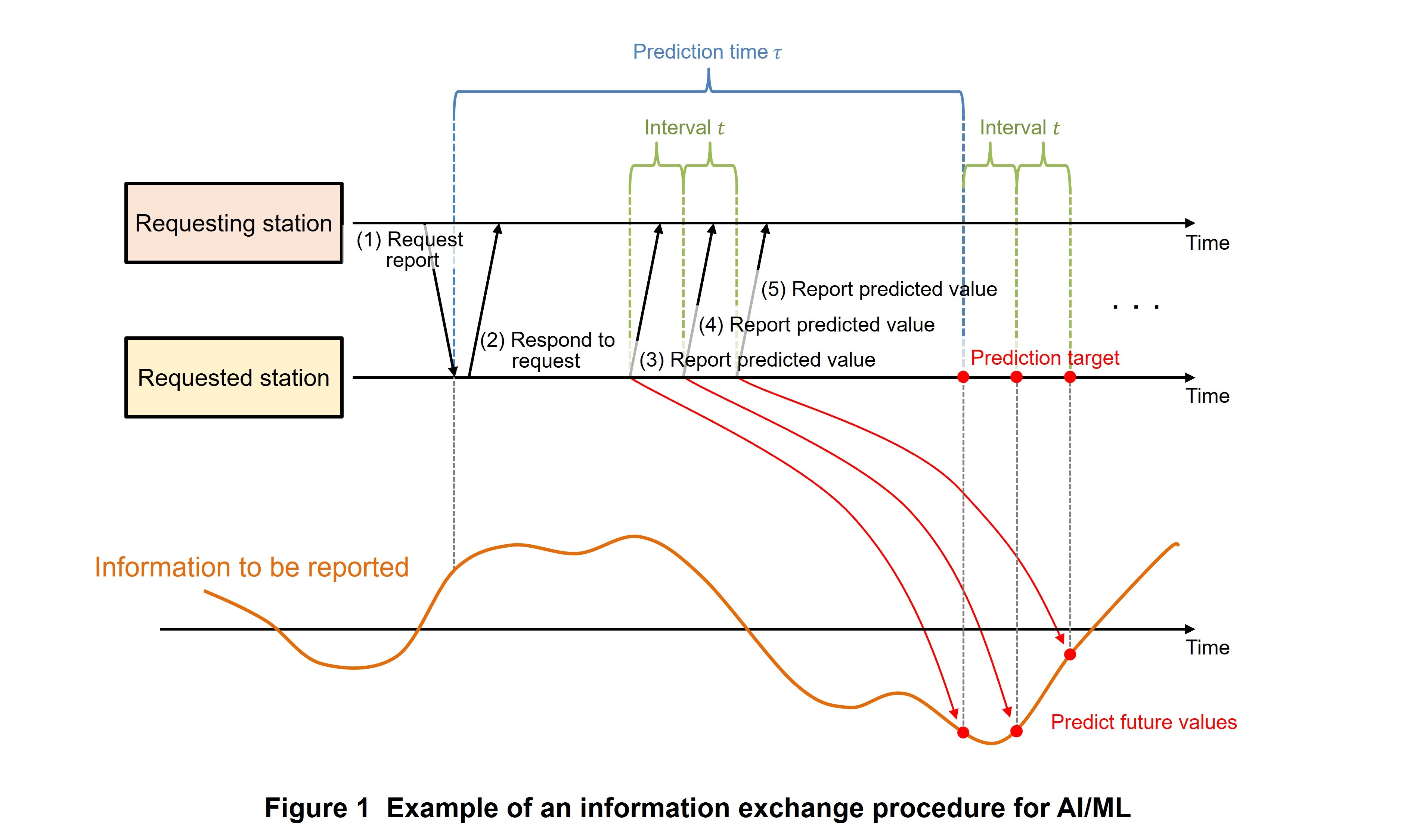
This is an XnAP message in which the requested base station sends a report (Data Collection Update) according to the request received from the requesting station in 1) above. For example, the procedure taken when a request is made for reporting a predicted value τ seconds ahead in t-second intervals is shown in Figure 1.
- The requesting station requests a report of predicted value τ seconds ahead in t-second intervals.
- The requested station responds that it has accepted the request.
- The requested station calculates the predicted value τ seconds ahead from the time point of receiving (1) and reports that value.
- The requested station calculates the predicted value t + τ seconds ahead from the time point of receiving (1) and reports that value t seconds later.
- The requested station calculates the predicted value 2t + τ seconds ahead from the time point of receiving (1) and reports the predicted value t seconds later.
2.2 Energy Saving
The reporting of Energy Cost described above as a function for reducing the power consumed by base stations has been specified. A base station that directly compares its own Energy Cost with that of another base station can learn how much each base station consumes energy. This information can be used, for example, to perform load balancing by changing the accommodation of UEs within an area and turning one cell off. This can achieve control that minimizes the total amount of power consumed by all base stations in a specific area. However, how a base station should behave using the reported Energy Cost is not specified.
Energy Cost is calculated based on current base-station power consumption and is reported as an integer value in the range of 0-10,000. The power values (e.g., kW) corresponding to these integer values are configured beforehand in the base station by OAM. As an example of a method for making these base-station settings, OAM can set the minimum value of actual base-station power consumption corresponding to minimum Energy Cost, i.e., 0 and the maximum value of actual base-station power consumption corresponding to maximum Energy Cost, i.e., 10,000 in the base station together with the time length for averaging out the power consumed. This calculation method uniformly configures Energy Cost in all base stations that are capable of exchanging Energy Cost values in a specific area.
2.3 Load Balancing
A UE Performance report was specified as a function for enabling a base station to perform more appropriate load balancing control. Here, UE Performance means performance information collected per UE including DL/UL average throughput, average transmission delay, and average DL packet loss rate. However, UE Performance is distinct from similar report information collected per base station as described in section 2.1.
In load balancing, the base station issues a handover instruction to the UE and accommodates the UE in a neighboring or overlapping cell with appropriate balance. However, there are cases in which a handover performed for load balancing deteriorates the communication quality of the UE. This function of making a UE Performance report feeds back information to the handover source base station on how UE communication quality might change when the base station issues a handover instruction to the UE for load balancing. Providing such information is expected to achieve more optimal load balancing control.
The preparation of a report that collects base-station information as described above begins immediately after receiving a request from the requesting station, but in the case of a UE Performance report, measurements and reporting are performed at different occasions. The measurement of UE Performance begins when the handover of the targeted UE from the requesting station to the requested station is executed and communication is established with the requested station. Then, as long as the UE is located in the requested station area, measurements will be performed only for the configured measurement duration and measurement results will be reported to the requesting station. The requesting station can configure the duration of these measurements in the UE Performance Collection Configuration described above.
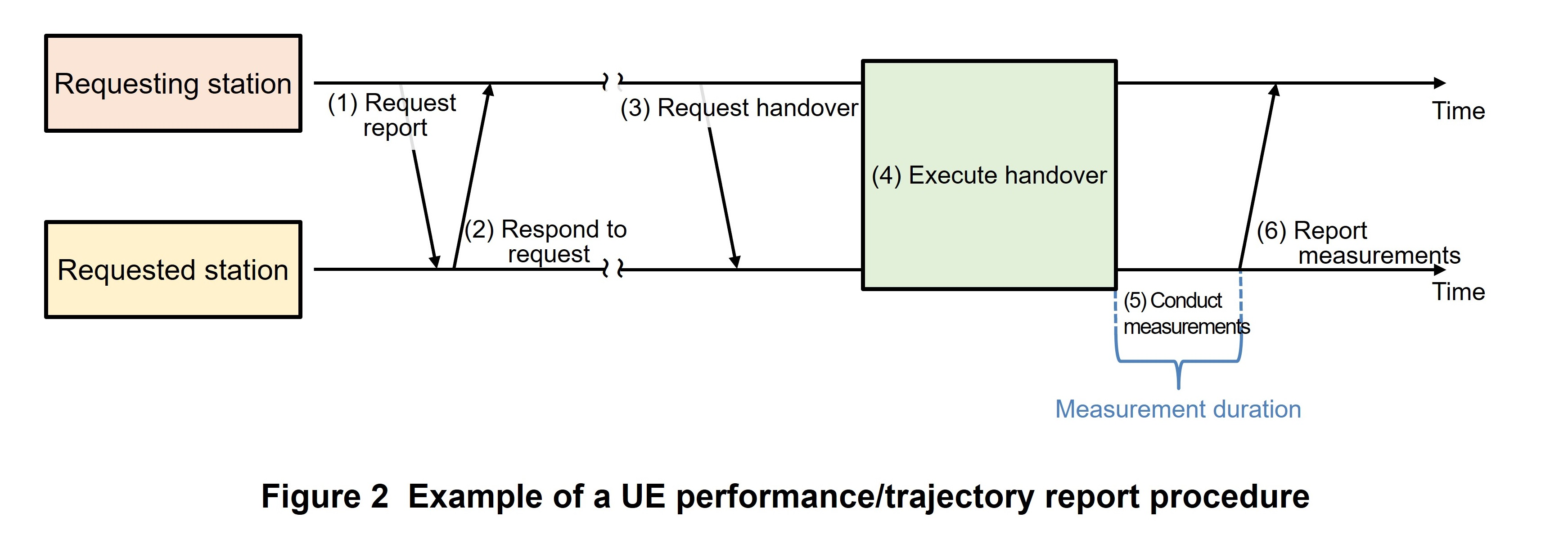
An example of the above procedure is shown in Figure 2.
- The requesting station requests a UE Performance report.
- The requested station responds that it has accepted the request.
- The requesting station sends a handover request and the requested station accepts the request.
- The target UE undergoes a handover from the requesting station to the requested station.
- The requested station measures UE Performance from the time that (4) completes but only for the configured measurement duration.
- Measurements complete when the specified measurement duration expires and the requested station reports measurement results to the requesting station.
2.4 Mobility Optimization
The UE Trajectory report mentioned above was specified as a function for the base station to perform more appropriate mobility control. In existing cellular communications, mobility control is basically achieved by determining the handover target cell and handover period based on measurement reports received by the base station from the UE and instructing the UE accordingly. Additionally, from Rel-16 on, the mobility functions Conditional HandOver (CHO)*9, Conditional PSCell Addition or Change (CPAC)*10, and L1/L2 Triggered Mobility (LTM)*11 were introduced for setting multiple cells as handover target candidates in UE. Here, the way in which those candidates are selected may affect the user experience. At the same time, higher frequency bands are coming into use and the trend is toward a shorter cell radius, so mobility control is becoming increasingly important for executing handovers while maintaining large-capacity and low-latency capabilities. The purpose of this function is to optimize mobility control by exchanging predicted UE trajectory and measured UE trajectory between base stations.
This function consists of a 1) Predicted UE Trajectory report and 2) Measured UE Trajectory report. An example of a UE trajectory report procedure is also shown in Fig. 2.
1) Predicted UE Trajectory Report
The requesting station, on deciding to hand over the target UE to the requested station, predicts the trajectory the UE will make in its transition to a cell under the requested station and reports that prediction to the requested station. This report is sent with the message at step (3) in Fig. 2. Then, after the target UE completes its handover to the cell under the requested station (Fig. 2 (4)), the requested station can refer to that prediction when setting up another handover thereby achieving more optimal mobility control. However, the behavior of the requested station on receiving this prediction has not been specified.
2) Measured UE Trajectory Report
Given the UE cell trajectory predicted by the requesting station, the requested station can report on the actual cell trajectory taken by the UE. This report can be used as feedback with respect to the cell trajectory prediction made by the requesting station to help improve the accuracy of its UE cell trajectory prediction. However, the behavior of the requesting station on receiving this feedback has not been specified.
In the same manner as described above, the requesting station can configure the method for measuring UE cell trajectory in UE Trajectory Collection Configuration. This instruction consists of measurement duration and number of trajectory cells. After the target UE completes its handover from the requesting station (Fig. 2 (4)), the requested station records the target UE cell trajectory as long as the target UE is located under the requested station and up until measurement duration expires or the target UE makes a transition to one more cell than the configured number of trajectory cells (Fig. 2 (5)). When this recording ends, the requested station reports actual UE cell trajectory to the requesting station (Fig. 2 (6)).
2.5 Standardization Discussions on Future AI/ML Functions
As described above, a variety of XnAP functional extensions were specified in Rel-18 for achieving base station control using AI/ML. Going forward, the application of AI/ML to cellular communications is expected to attract even more attention, so further functional extensions are anticipated in Rel-19. Specifically, it is anticipated that the following items for which specifications could not be made in Rel-18 will be discussed in Rel-19.
- Optimization of mobility control in a New Radio Dual Connectivity (NR-DC)*12 state
- Support of Central Unit Distributed Unit (CU-DU) split architecture*13
- Energy Cost prediction
- Continuous collection of Minimization of Drive Tests (MDT)*14 across changes in the RRC connection state for the same UE
- UE cell trajectory across multiple base stations
Moreover, in addition to the three use cases of energy saving, load balancing, and mobility optimization described above, discussions are expected to be held in Rel-19 on functional extensions for network slicing*15 and Coverage and Capacity Optimization (CCO)*16.
- Inter-base-station signaling: Control signals used for communications between base stations.
- OAM: Functions for maintenance and operational management on a network.
- XnAP: Protocol that specifies the application layer from among Xn interfaces that interconnect base stations in NR.
- Handover: The communication technology that performs switching between cells and base stations while maintaining communications between the UE and the network.
- RRC: Layer 3 protocol that controls radio resources on the radio network.
- CHO: An operation that sets candidate cells for executing a handover and handover execution conditions so that the UE can autonomously execute the handover when those execution conditions are satisfied.
- CPAC: A procedure specified in Rel-17 for adding or changing a PSCell. The UE adds or changes the target PSCell when the execution conditions set in the UE are satisfied.
- LTM: A newly specified handover procedure in Rel-18 that uses beam measurements and reports by the UE using L1 as a basis for instructing cell/beam using L2 from among the handover candidate cells specified beforehand by the base station.
- NR-DC: The execution of DC—technology that connects a single terminal to multiple base stations using different frequency bands—between two NR base stations.
- CU-DU split architecture: Architecture introduced in NR that functionally splits a base station into a CU and DU.
- MDT: Technology standardized in 3GPP whereby a UE notifies the network of location information corresponding to the occurrence of phenomena such as communication disconnections, handover failures, etc. and their causes for the collection of Quality of Experience (QoE) data.
- Network slicing: One form for achieving next-generation networks in the 5G era by logically dividing the network into units of services corresponding to use cases, business models, etc.
- CCO: Technology for optimizing coverage and communication capacity.
-
Reduction of power consumption on the network side has become a major ...
Open
Reduction of power consumption on the network side has become a major issue for operators owing to social demands arising from heightened awareness of environmental problems in recent years and to more antennas, larger bandwidths, and more frequency bands accompanying advances in wireless networks. As a technology for reducing power consumption on the network side, NES was specified for the first time in Rel-18. It consists of technologies for actually achieving power reductions and control technology for achieving smooth operations when applying those technologies to a network. In this way, it should be possible to bolster energy-saving effects on the network side and provide a network that minimizes operational costs while taking the environment into account.
3.1 Power Reduction Technologies in the Spatial and Power Domains
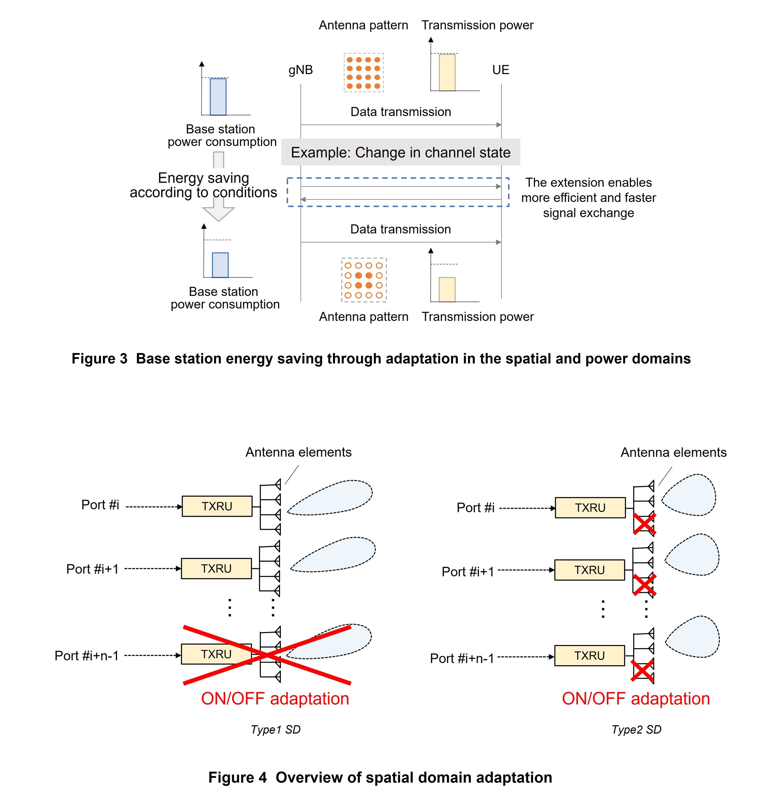
Spatial Domain (SD) adaptation and Power Domain (PD) adaptation were specified as power reduction technologies in the spatial and power domains. From the viewpoint of network energy saving, it is desirable to turn off a number of antenna elements used for data transmission depending on UE conditions and to reduce data transmission power so as to reduce power consumption in the base station's Transceiver Unit (TXRU)*17 and Power Amplifier (PA)*18. This release introduced a mechanism that enables the base station to determine the appropriate number of antennas and transmission power according to UE conditions more efficiently and faster than the existing mechanism. This new mechanism is expected to enable the base station to keep the number of antennas and transmission power used for data transmission to a UE down to a bare minimum according to UE conditions to achieve base station energy saving (Figure 3). However, the number of antennas, the antenna pattern, and transmission power actually used by a base station for transmission is determined by that base station's implementation and is not stipulated in 3GPP specifications.
A base station needs to understand the UE's channel state to determine the appropriate number of antennas and transmission power according to UE conditions. To obtain the UE's Channel State Information (CSI)*19, a CSI report mechanism has been specified in which the UE measures a CSI-Reference Signal (CSI-RS)*20 transmitted from the base station, calculates CSI, and reports those results to the base station. However, to enable more efficient and quicker spatial and power adaptation according to current conditions, this mechanism was extended to enable (1) a CSI report to be made all at once for multiple antenna patterns and (2) a CSI report to be made all at once for multiple Physical Downlink Shared CHannel (PDSCH)*21 transmission power values.
1) Background and Overview of Spatial Adaptation
In the case of an NR massive Multiple Input Multiple Output (MIMO)*22 system, we can consider an antenna configuration that forms multiple antenna elements into a subarray*23 and uses multiple subarray antennas. In such a configuration, two types of spatial-domain adaptive control methods can be considered with respect to spatial elements mapped from logical antenna ports (here, this refers to TXRUs and the physical antenna elements connected to each of them). One is called Type 1 SD adaptation, which is adaptive control that turns all spatial elements linked to certain logical antenna ports ON/OFF (Figure 4 left). The other is called Type 2 SD adaptation, which is adaptive control that turns some spatial elements linked to certain logical antenna ports ON/OFF (Fig. 4 right). As shown in the figure, these two types of spatial adaptive control differ in the effect each has on the beams formed on the base-station side through these ON/OFF operations. In Rel-18, necessary extensions were made to the CSI report to handle each of these two types of spatial adaptive control methods. Specifically, the UE calculates and reports the CSI for each of the ON/OFF control patterns of the spatial elements so that the base station can achieve appropriate spatial adaptive control according to current conditions.
2) Background and Overview of Power Adaptation
In existing CSI report specifications, a UE calculates CSI and reports results to the base station in the following way. First, to derive the PDSCH assumed power value, which is information needed by the UE to calculate CSI, the CSI-RS and PDSCH relative power value is set as one parameter by the base station. The UE measures CSI-RS, and based on the quality of the measured CSI-RS, calculates CSI including Channel Quality Indicator (CQI)*24, Precoding Matrix Indicator (PMI)*25, and Rank Indicator (RI)*26 for the case that PDSCH is transmitted with the assumed power value and then reports calculation results to the base station. Then, based on this CSI report, the base station can determine the parameters to be applied to the PDSCH to be transmitted to the UE that created that report. Here, by setting multiple assumed PDSCH power values in the UE and by having the UE simultaneously report CSI for each of those power values, it is expected that the base station will be able to determine the effects on CSI when performing power adaptive control and therefore achieve appropriate transmission power control according to current conditions.
In Rel-18, extensions to the CSI report were also made in power adaptive control using a common framework with respect to extensions to the CSI report for spatial adaptive control.
3) Extensions to CSI Report
The concept of a sub-configuration was introduced to enable efficient creation of a CSI report for multiple antenna patterns and multiple transmission power values. A single sub-configuration can be viewed as a combination of a certain antenna pattern and PDSCH transmission power as information needed by a UE to calculate CSI. The base station sets multiple sub-configurations in the UE according to the CSI report configuration, and the UE, which performs CSI-RS measurements and CSI calculations based on those settings, issues a CSI report that includes multiple CSI sub-reports linked to each sub-configuration.
In addition, parameters related to spatial adaptive control (Type 1 SD or Type 2 SD) and parameters related to power adaptive control (PD) can be simultaneously set in a sub-configuration. Each of these parameter settings and the method used to report CSI to the base station are explained below.
- In parameters related to Type 1 SD, to represent the ON/OFF combination pattern for each of multiple logical antenna ports, subset patterns of CSI-RS antenna ports, their respective number of ports, and limitations to the codebook*27 and rank*28 number corresponding to each subset pattern are set based on existing parameters. The base station transmits CSI-RSs for certain numbers of logical antenna ports and logical-antenna-port patterns, and based on settings from the base station, the UE calculates CSIs for multiple patterns that are subsets (where a subset corresponds to a portion of logical antenna ports turned off) of all available antenna patterns and reports those results all together. This scheme enables the base station to efficiently obtain CSIs for multiple ON/OFF patterns.
- In parameters related to Type 2 SD, to represent the ON/OFF patterns of multiple antenna elements, a CSI-RS resource*29 linked to each pattern within the CSI-RS resource is set as a measurement target. An ON/OFF pattern of some antenna elements linked to a logical antenna port are not stipulated in specifications and depend on base station implementation, so that pattern is expressed by specifying it as a CSI-RS resource transmitted by the base station. As a result, multiple CSI-RS resources are needed to have the UE measure multiple antenna-element ON/OFF patterns, but since the UE reports CSIs for those patterns all together, the base station is able to efficiently obtain CSIs.
- In parameters related to PD, a CSI-RS resource set is configured as a measurement target linked to each sub-configuration and a PDSCH relative power value assumed for a single CSI calculation is also set.
The UE uses the CSI report sub-configuration settings described above to report at one time CSI sub-reports for combinations of antenna patterns and transmission power as a CSI report. Rules have been specified for mapping multiple sub-reports in a single CSI and extensions have been made to rules on the number of processes that the UE can support as operations related to CSI-RS reception, CSI calculation, etc.
4) Extensions to CSI Triggering
Three types of methods (periodic, semi-persistent, and aperiodic) have been specified as report-time operations for existing CSI reports. Three trigger methods that differ according to these three types of report-time operations have also been specified for the time that the base station requests the UE for a CSI report. These are RRC, Medium Access Control Control Element (MAC CE)*30, and Downlink Control Information (DCI)*31. The following extensions were made to each of these trigger methods along with the introduction of sub-configurations.
- For periodic CSI reports triggered by RRC, the UE reports CSIs for all sub-configurations set beforehand.
- For semi-persistent CSI reports using the Physical Uplink Control CHannel (PUCCH)*32 triggered by MAC CE, the sub-configuration targeted for a report from a list set in the UE beforehand by extended MAC CE will be indicated.
- For semi-persistent/aperiodic CSI reports using the Physical Uplink Shared CHannel (PUSCH)*33 triggered by DCI, a single trigger state from the trigger state*34 list set in the UE beforehand by DCI will be indicated. This extended trigger state can specify a list of sub-configurations targeted for reports.
3.2 Power Reduction Technology in the Frequency Domain
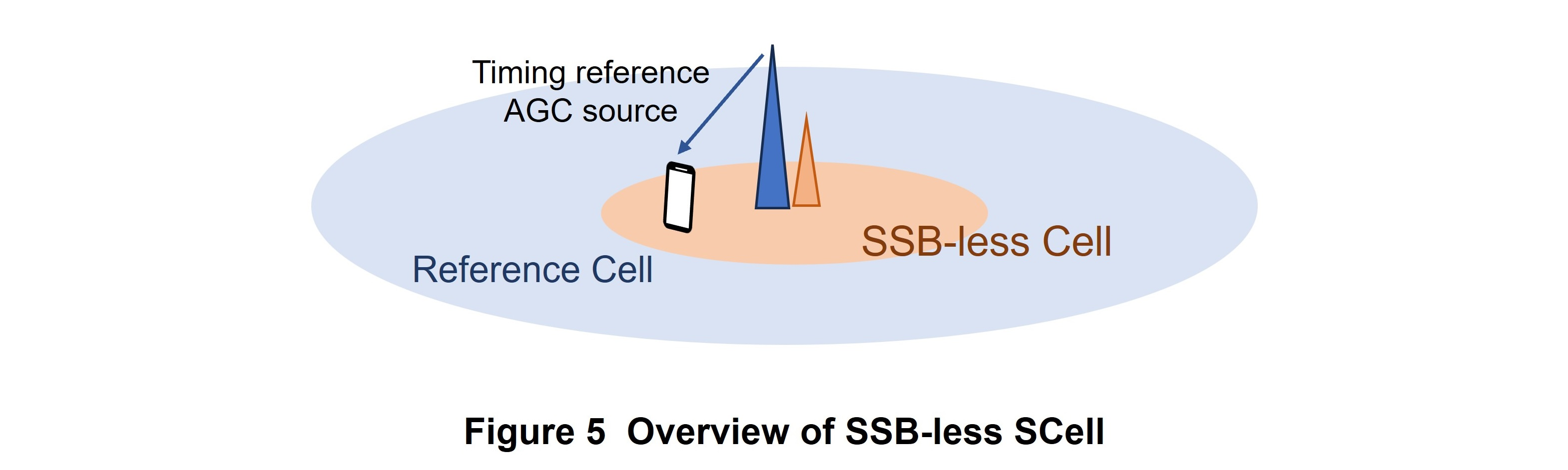
As a power reduction technology in the frequency domain*35, an inter-band*36 Carrier Aggregation (CA)*37, Synchronization Signals/Physical Broadcast CHannel Block (SSB)*38 -less Secondary Cell (SCell)*39 is specified. The aim here is to increase the probability that the base station enters a sleep state and reduces power consumption by having it reduce common signals that need to be transmitted periodically.
When the network does not transmit SSB in a certain SCell, the UE can reference another cell situated at the same point for synchronization information and an Automatic Gain Control (AGC)*40 source (Figure 5). At this time, the network side can specify a Reference Cell through RRC.
3.3 Power Reduction Technology in the Time Domain
As power reduction technology in the time domain*41, Cell Discontinuous Transmission (DTX)*42 /Discontinuous Reception (DRX)*43 was newly specified. In Rel-18 Cell DTX/DRX, a time is established during which a portion of transmit/receive operations performed periodically by the base station in a certain cell with respect to an RRC Connected*44 UE is not performed so that the base station can enter a sleep state and reduce power consumption.
Cell DTX/DRX specifications mainly consist of (1) setting of various parameters for UE, (2) application of Cell DTX/DRX, and (3) alignment with UE Connected DRX (C-DRX)*45.
1) Setting of Various Parameters for UE
Cell DTX/DRX parameter settings are made through RRC. For each UE serving cell*46 within an RRC reconfiguration, the UE can set application type (Cell DTX, Cell DRX, or both), Cell DTX/DRX period (DTX/DRX pattern), timing adjustment at application time, and operation state (deactivated/activated). “Timing adjustment at application time” is a parameter that is needed for alignment between Cell DTX/DRX and UE C-DRX described later.
Additionally, “Cell DTX/DRX period” can only take on a maximum of two different values for each MAC Entity*47 with the following constraints:
- “Timing adjustment at application time” is common to both
- One period must be an integer multiple of the other period
These constraints were set to avoid complexity in UE implementation considering existing UE C-DRX operation during CA.
2) Application of Cell DTX/DRX
A method using RRC and a method using DCI exist for Cell DTX/DRX activation/deactivation. In either method, the network explicitly notifies the UE of activation/deactivation. However, a mechanism that monitors the communication state like C-DRX in UE and autonomously enters an activation/deactivation state when a non-communication state continues for a certain length of time was not introduced in Rel-18.
In the method using RRC, RRC reconfiguration can be used to set activation/deactivation for each serving cell and each UE. In this method, in the event that a certain cell changes the application of Cell DTX/DRX, an RRC reconfiguration must be executed for all UEs within the cell.
The method using DCI makes use of newly defined DCI format 2_9 consisting of multiple information blocks. One of these blocks notifies of a change in operation state of a certain UE in a certain serving cell. In addition, the base station can specify through an RRC configuration what information block can be referenced at what position in a DCI format 2_9 bit sequence for each serving cell of a UE. As a result, a single DCI format 2_9 notification can indicate changes in cell operation information for multiple UEs simultaneously, which means that instructions can be issued more efficiently than issuing instructions on changes multiple times by the method using RRC described above.
3) Alignment with UE C-DRX
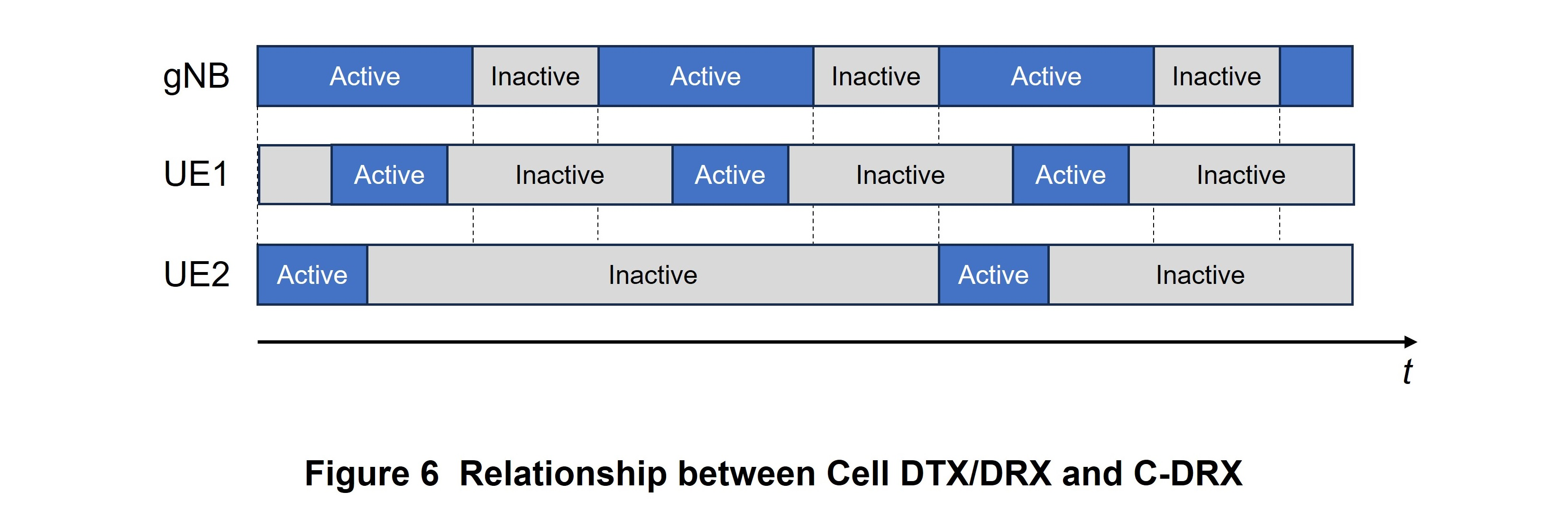
Cell DTX should be set taking UE C-DRX into account. To give an extreme example, if UE is always in an inactive (sleep) state while the network side is in an active (wake up) state, no communication can be performed. “Power consumption reduction” and “user experience” in UE can therefore be maximized when applying Cell DTX by appropriately setting the period and timing of Cell DTX on the network side and that of UE C-DRX (Figure 6). For this reason, Cell DTX/DRX timing and UE C-DRX timing can be aligned by specifying Cell DTX/DRX start timing when setting parameters as described above.
In addition, the following constraint is applied with respect to period: “the period of either Cell DTX/DRX or UE C-DRX must be an integer multiple of the other period.”
3.4 Barring of Existing UE
In the event that UE that does not support Cell DTX/DRX functions connects to a cell that is currently applying Cell DTX/DRX, coordinating operations cannot be performed between the network and UE. For this reason, a barring*48 function was specified to bar an existing UE that does not support Cell DTX/DRX functions. This function is used together with barring bits that target all UEs in the Master Information Block (MIB)*49 and the barring bits added for UE having NES functions in System Information Block (SIB)*50 1. Specifically, operations that permit only UEs supporting Cell DTX/DRX can be achieved by restricting access to all UEs marked as “barred” in MIB and by marking UEs having NES functions as “not barred” in SIB 1.
3.5 Extensions to CHO from Viewpoint of NES
When applying NES functions in an operating cell, there are cases in which a handover must be performed for a camped UE (for example, to apply Cell DTX/DRX, to suspend operation of the cell itself, etc.). Taking such cases into account, specification extensions were made to CHO introduced in Rel-16 from the viewpoint of NES.
If a CHO needs to be executed owing to NES functions, the network sets beforehand a CHO trigger in the UE such that a NES-related event becomes the condition for that CHO. A bit indicating CHO execution in the newly designed DCI format 2_9 is used to determine this NES-event condition. To execute CHO due to NES, the cell transmits DCI format 2_9 with the bit triggering CHO execution turned on. This activates the CHO trigger for NES events at the UE receiving this information.
- TXRU: Modeling of a transmission antenna unit up to physical antenna elements such as a digital beamforming unit. Not directly stipulated in 3GPP specifications.
- PA: A circuit that amplifies power for transmitting a Radio Frequency (RF) signal from an antenna with sufficient power.
- CSI: Information describing the state of the radio channel traversed by the received signal.
- CSI-RS: A known reference signal transmitted for measuring the state of the radio channel.
- PDSCH: A physical channel for transmitting user data and control information from higher layer signaling.
- Massive MIMO: A generic term for MIMO transmission technologies using very large numbers of antennas. MIMO is a signal technology that improves communications quality and spectral efficiency by using multiple transmitter and receiver antennas to transmit signals at the same time and same frequency.
- Subarray: In this article, a configuration in which multiple antenna elements connect to a single logical antenna port or the TXRU.
- CQI: An index of reception quality measured at the mobile station, expressing propagation conditions on the DL.
- PMI: Information fed back from the mobile terminal on precoding assumed to be optimal for the DL.
- RI: In this article, information for the UE to report a suitable number of transmit streams to the base station.
- Codebook: In this article, a set of predetermined precoding-weight matrix candidates so that the UE can report a suitable DL precoder to the base station.
- Rank: In this article, information for the UE to report a suitable number of transmit streams to the base station.
- CSI-RS resource: Settings that group together time/frequency resources, number of antenna ports, etc. for transmitting a CSI-RS.
- MAC CE: A particular configuration control signal transmitted on the MAC sublayer.
- DCI: Control information transmitted on the DL that includes scheduling information needed by each user to demodulate data and information on data modulation and channel coding rate.
- PUCCH: Physical channel used for sending and receiving control signals in the UL.
- PUSCH: Physical channel used for sending and receiving data packets on the UL.
- Trigger state: An RRC setting for aperiodic CSI reporting that associates the CSI-RS setting targeted for measurement with the CSI report setting.
- Power reduction technology in the frequency domain: Technology that aims for energy savings by suppressing the transmitting/receiving of signals in a specific frequency.
- Inter-band: A scenario for performing communications using multiple carriers in different frequency bands.
- CA: A technology that achieves higher transmission speeds by transmitting and receiving data using multiple carriers supported by a single base station.
- SSB: A synchronization-signals/broadcast channel block consisting of SS and PBCH. It is periodically transmitted mainly for detecting cell ID and reception timing when the UE begins communications, and in NR, it can also be used for measuring reception quality in each cell.
- SCell: Generic name for a component carrier that is neither a Primary Cell (PCell) nor a Primary Secondary Cell (PSCell) among the multiple carriers used in CA. A PCell is a component carrier that guarantees connectivity among the multiple carriers used in CA while a PSCell is a component carrier that guarantees connectivity among the component carriers supported by the secondary base station in DC.
- AGC: Control that maintains the output at a fixed level independent of the level of the received input signal.
- Power reduction technology in the time domain: Technology that aims for energy savings by suppressing the transmitting/receiving of signals during a specific time.
- DTX: Intermittent transmission to reduce power consumption.
- DRX: Intermittent reception to reduce power consumption.
- RRC Connected: One type of UE RRC state indicating that the UE is in a connected state with the base station.
- C-DRX: UE-side DRX in an RRC Connected state.
- Serving cell: Refers to the PCell and SCells when a UE is configured for CA, and just the PCell when not configured for CA.
- MAC Entity: A sublayer in Layer 2 and an operational unit in MAC protocol that performs radio resource allocation, data mapping, resend control, etc.
- Barring: Indicates the restricting of access. When connection is to be restricted due to circumstances on the network side, it is a mechanism in which the UE itself determines whether it is a target of restriction based on a signal notification from the network and does not transmit connection requests if so.
- MIB: System information broadcast simultaneously from the radio base station to UEs to enable the reception of notifications. It includes cellBarred status information, physical layer information, etc.
- SIB: A type of notification broadcast simultaneously from the radio base station to UEs divided into units of radio blocks. The SIB 1 block includes UL carrier information for random access, random-access-signal configuration information, etc.
-
Reduction of power consumption on the network side has become a major ...
Open
With a view to further development of the 5G area and expansion of coverage*51, Rel-17 established NR repeater specifications. This NR repeater*52 follows the repeaters from the 2nd Generation mobile communications system (2G) to the 4th Generation mobile communications system (4G) and features functions for amplifying and forwarding signals transmitted and received between a base station and UE. In Rel-17 specifications, however, the role of a NR repeater is simply to amplify and forward signals. In other words, no repeater operations or functions were specified, so in Rel-18, NCR was specified as a repeater with a new format in which the network controls a portion of repeater operations. In this way, further extensions and higher densities are expected for the NR network such as repeater beam control and repeater operation in even higher frequency bands.
4.1 NCR Architecture
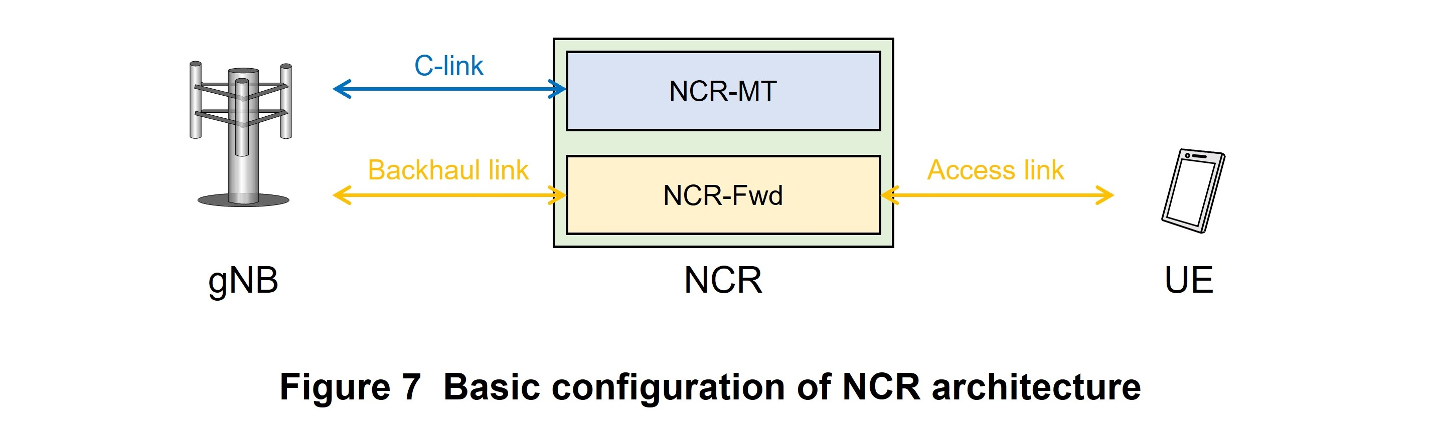
The basic configuration of NCR architecture is shown in Figure 7 [2]. As shown in the diagram, NCR consists of Mobile Termination (NCR-MT) having functions equivalent to those of UE and RF Forwarding (NCR-Fwd) corresponding to repeater functions for amplifying and forwarding signals. The link between NCR-MT and the gNodeB (gNB)*53 is defined as the Control link (C-link). The NCR-MT function transmits and receives control information and data the same as an ordinary UE and receives side control information that controls NCR-Fwd. In addition, the link between NCR-Fwd and gNB and that between NCR-Fwd and UE is defined as a backhaul link and access link, respectively. The NCR-Fwd function amplifies base-station transmission signals received on the backhaul link or UE transmission signals received on the access link and transmits those signals on the access link or backhaul link.
4.2 NCR Operating Procedures
NCR begins operations based on the following three procedures [3].
- NCR-MT network connection
The NCR-MT component connects to the network based on the same procedure as UE with respect to a cell that supports NCR. - NCR setup
The gNB-CU sets up NCR through RRC. - Begin NCR operations
After completion of NCR setup, the NCR begins power amplification operations with respect to UE.
4.3 Physical Layer Functions
The following four NCR preconditions were established when drafting NCR specifications.
- First, the C-link and backhaul/access links must operate at the same frequency and NCR-Fwd must be able to operate under this condition according to the NCR-MT setup.
- Second, NCR is a fixed installation (immobile) and a maximum of one NCR unit shall be inserted between the gNB and UE.
- Third, the UE is unaware of NCR existence and no special control is needed for the UE even if an NCR happens to be inserted.
- Fourth, the NCR must be able to operate the backhaul link and access link simultaneously and it is assumed that received signals are immediately amplified and transmitted.
NCR control and operations using side control information were specified based on the above four conditions.
1) Beam Indication for Access Link
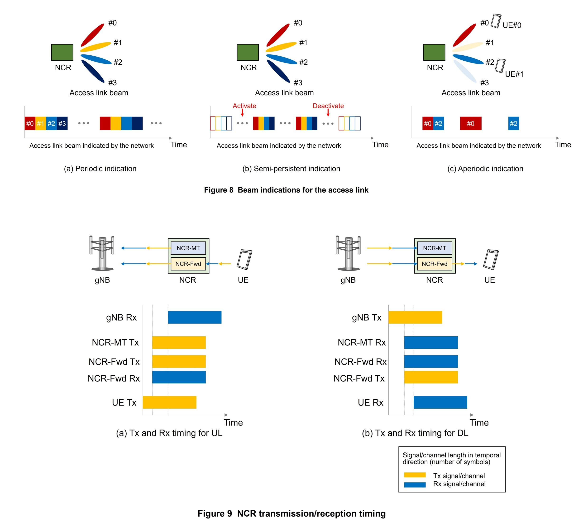
The network can set a maximum of 64 beams for the access link, and information such as the number of access-link beams supported by NCR is passed to the network using OAM. To enable the network to indicate the beams and time-domain resources to be applied to the access link using side control information, three methods have been specified as shown in Figure 8.
- The first method is periodic indication for use in amplifying and forwarding cell-specific, periodic signals/channels such as SSB and Physical Random Access CHhannel (PRACH)*54. As shown in Fig. 8 (a), a combination of an access-link beam index and time-domain resource to be applied can be set for multiple beams, which is set by RRC together with period information for applying the settings.
- The second method is semi-persistent indication for use in amplifying and forwarding semi-static signals/channels. Similar to periodic indication, multiple combinations of access-link beam indices and time-domain resources to be applied are set by RRC together with period information, and activation and deactivation of settings are indicated using MAC-CE (Fig. 8 (b)).
- The third method is aperiodic indication for use in amplifying and forwarding UE-specific signals/channels allocated to a particular UE. This method sets the access-link beam index and time-domain resource to be applied using DCI format 2_8 scrambled*55 by NCR Radio Network Temporary Identifier (NCR-RNTI)*56 (Fig. 8 (c)).
Access-link beams can be indicated by the above three methods, but to indicate priority for the case of duplicate settings, a priority flag can be set in periodic indication and semi-persistent indication. Here, priority in descending order is semi-persistent indication with priority flag set, periodic indication with priority flag set, aperiodic indication, semi-persistent indication with no priority flag set, and periodic indication with no priority flag set.
2) Beam Indication for Backhaul Link
As NCR beam indication methods for the backhaul link, operations are specified for the case of simultaneous transmission/reception and the case of no simultaneous transmission/reception by NCR-MT and NCR-Fwd.
First, for the case of simultaneous transmission/reception, the same beam as the beam set in the NCR-MT C-link is applied to the backhaul link.
Next, for the case of no simultaneous transmission/reception, if a beam is set in NCR-MT using the Unified Transmission Configuration Indication (TCI) state*57 introduced in Rel-17, that beam is applied to the backhaul link. Additionally, for the case of no simultaneous transmission/reception, if beams are set in NCR-MT by the method introduced in Rel-15, the beam set in COntrol REsourceSET (CORESET)*58 for reception and the beam set in PUCCH for transmission are respectively set as beams for the backhaul link. Beam indication for the transmission and reception beams on the backhaul link can also be performed using MAC-CE.
3) NCR-Fwd ON/OFF Operation
To support NCR energy-saving operation, NCR-Fwd ON/OFF operation was specified. The NCR-Fwd default operation is OFF and the NCR-Fwd function operates only for a time-domain resource having a beam indication for the access link.
4) NCR-Fwd Transmission/Reception Timing
The NCR-MT and NCR-Fwd UL/DL transmission/reception timing is shown in Figure 9. As shown in Fig. 9 (a) for the UL, gNB receives UE transmission signals and NCR-MT transmission signals with the same timing, so NCR-MT and NCR-Fwd transmission timings are the same. As a result, NCR-Fwd transmission timing conforms to NCR-MT transmission timing controlled by gNB. Similarly, as shown in in Fig. 9 (b) for the DL, timing for receiving gNB transmission signals is the same for NCR-MT and NCR-Fwd. As a result, NCR-Fwd reception timing conforms to NCR-MT.
Furthermore, when introducing NCR in a network operated by the Time Division Duplex (TDD)*59 transmission method, NCR-Fwd operates according to the TDD pattern set in NCR-MT. If the TDD pattern set in NCR-MT is only on the UL, NCR-Fwd receives UE transmission signals by the access link and transmits amplified signals to gNB by the backhaul link. Similarly, if the TDD pattern set in NCR-MT is only on the DL, NCR-Fwd receives gNB transmission signals by the backhaul link and transmits amplified signals to UE by the access link.
5) NCR-MT Operation
The NCR-MT component has the same functions as an ordinary UE and performs initial access and transmission/reception of control information and data the same as UE. However, as an NCR-unique operation, if a link recovery procedure*60 occurs in NCR-MT due, for example, to degradation in C-link radio quality, NCR-Fwd performs no transmission/reception until that procedure completes. Additionally, for the case that NCR does not support simultaneous transmission on the C-link and backhaul link, NCR-Fwd performs no transmission by the time-domain resource used by NCR-MT for transmission.
- Coverage: The area (cell radius) in which communications with UEs per base station can be carried out. The greater the coverage, the fewer the number of base stations to be installed.
- NR repeater: A node for amplifying and forwarding radio signals transmitted/received between a base station and UE extended for NR.
- gNB: 5G NR base station.
- PRACH: Physical channel for transmission when the UE establishes a connection with a cell, for example, for initial access or handover.
- Scrambled: Randomizing by a process that multiplies code sequences.
- NCR-RNTI: Identifier assigned to NCR.
- Unified TCI state: Method for setting a transmission configuration indication state for multiple UL/DL channels/signals.
- CORESET: Resource set for transmitting a DL control channel.
- TDD: A signal transmission method in which the same carrier frequency or frequency band is partitioned into time slots used for UL and DL.
- Link recovery procedure: Procedure for recovering from a link failure.
-
This article described AI/ML for NG-RAN, NES, and NCR as advanced ...
Open
This article described AI/ML for NG-RAN, NES, and NCR as advanced technologies in new areas introduced in Rel-18 NR. The introduction of Rel-18 NR including the functions described in this article is expected to further extend and enhance the 5G network. NTT DOCOMO will continue to support standardization activities at 3GPP to expand the development and spread of 5G.
-
REFERENCES
Open
- [1] 3GPP TR37.817 V17.0.0: “Study on enhancement for Data Collection for NR and EN-DC,” Apr. 2022.
- [2] 3GPP TS38.300 V18.0.0: “NR; NR and NG-RAN Overall Description; Stage 2,” Dec. 2023.
- [3] 3GPP TS38.401 V18.0.0: “NG-RAN; Architecture description,” Dec. 2023.

