
Special Articles on 3GPP Release 18 Standardization Activities (1)
Advanced Technologies for Industry Creation and Solution Co-creation in 3GPP Release 18
Vertical Network IoT NTN
Shohei Yoshioka and Mayuko Okano
6G Network Innovation Department
Tianyang Min
Radio Access Network Technology Promotion Office
Masaya Okamura and Kosuke Shima
Device-Tech Development Department
Abstract
The 3GPP Rel-16 and 17 specifications targeted a broad range of use cases and advanced solutions, and Rel-18 includes specifications aimed to create new industries and solutions for social issues. This article describes the specifications related to radio access technologies in 3GPP Rel-18 that will contribute to industry creation and co-creation of solutions.
01. Introduction
-
Technical study of 5th Generation mobile communications systems (5G) ...
Open

Technical study of 5th Generation mobile communications systems (5G) targeting industry collaboration has been conducted at the 3rd Generation Partnership Project (3GPP) for earlier releases to Release 17 (Rel-17). These releases included specifications for radio technologies for conventional mobile communications services, and also for services that support various industries and society or provide new value, such as Internet of Things (IoT) applications including smart factories*1, connected cars*2, and sensor networks, and use cases in new coverage areas such as in the air, on the sea, and in remote/mountainous areas. Rel-18 includes technical specifications to further expand the industry-collaboration domain and to advance solutions in this domain targeted in earlier releases.
This article describes background to the study of various solutions, mainly targeting industry collaboration (industry-collaboration solutions), and radio-related technical elements for implementing such solutions specified in 3GPP Rel-18.
- Smart factories: Factory systems in which all devices in an area are connected with each other by a highly reliable, low-latency radio network for automated control and other purposes.
- Connected car: A vehicle that is able to communicate with the outside world through a communication device.
-
This section summarizes the background and technical requirements ...
Open
This section summarizes the background and technical requirements of industry-collaboration solutions related to 3GPP Rel-18.
2.1 IoT
Earlier 3GPP releases to Rel-16 and Rel-17 have advanced and optimized radio technologies targeted to both high-end IoT services, such as Ultra-Reliable and Low Latency Communications (URLLC)*3 for Vehicle to everything (V2X)*4 and Industrial IoT (IIoT)*5 and UE positioning technology, and mid-range IoT services such as wearable devices called Reduced Capabilities (RedCap)*6 [1]. For Rel-18, technical study was conducted to further expand the range of applications for such IoT services, described as follows.
1) eRedCap (enhanced RedCap)
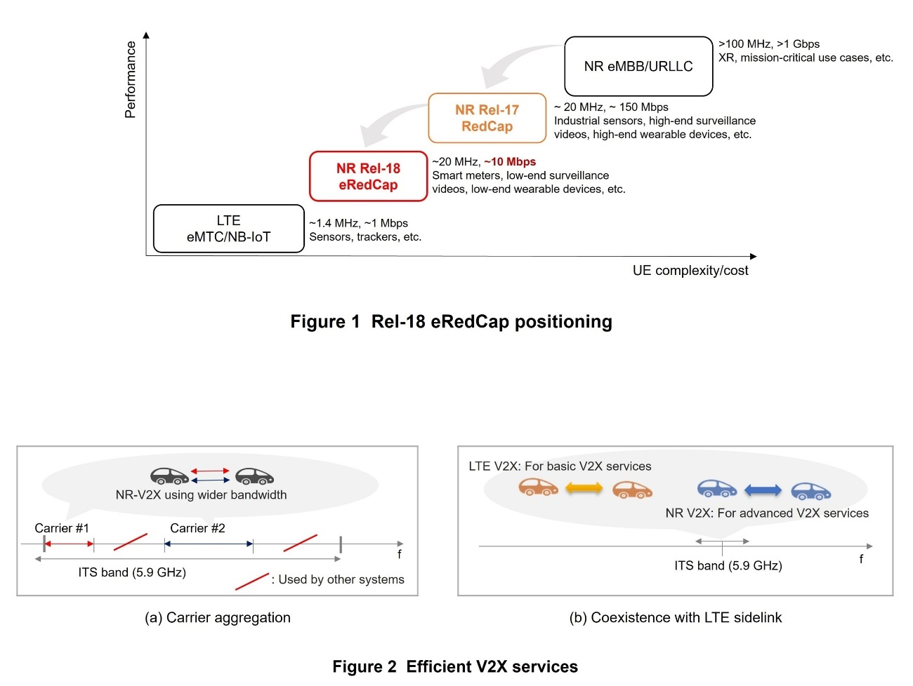
In Rel-17, specifications were optimized for RedCap UE, which have complexity and performance that is between high-end IoT UE with features such as New Radio (NR)*7 enhanced Mobile BroadBand (eMBB)*8 and URLLC; and low-end IoT UE with LTE-IoT features such as enhanced Machine Type Communication (eMTC)*9 and Narrow Band-IoT (NB-IoT)*10. However, new use cases, such as smart grid*11, have been conceived between RedCap and LTE-IoT, so Rel-18 has specified eRedCap, with further reduced UE complexity relative to RedCap, as shown in Figure 1.
2) Unmanned Aerial Vehicles (UAV)
Provision of new services using drones that connect to cellular networks has also begun in various business fields recently. In December 2022, revisions to the Civil Aeronautics Act came into effect and the ban on level 4 drone flight*12 was lifted, and thus drone usage scenarios continue to increase. With the need for high-speed, high-capacity communications for drones increasing, provisions for drone devices (UAVs) have been optimized in Rel-18. Maintaining the basic features of LTE UAV, more-advanced extensions to functionality have been added.
3) Sidelink
Sidelink*13 is a feature much anticipated for implementing IoT industry- collaboration solutions. Sidelink provisions for 5G included specifications for basic sidelink functionality for V2X in 3GPP Rel-16 [2]. Rel-17 added provisions for reduced power consumption features, high-reliability and low-latency features for pedestrians in V2X, public safety devices, and others. However, there have been many issues regarding practical use of IoT networks using sidelink, and it has not yet been in practical use broadly around the world. Based on these circumstances, further extensions to sidelink functionality have been added in Rel-18 to make sidelink services available. Specifically, functions for utilizing the 5-6 GHz unlicensed band*14, functions for sidelink carrier aggregation*15 and functions for co-existence of NR sidelink and LTE sidelink have been added, to increase data rates and expand applications. Sidelink carrier aggregation functions have been defined assuming that frequencies allocatable for cellular V2X within the Intelligent Transportation System (ITS)*16 band are non-contiguous, as shown in Figure 2 (a). Co-existence of NR sidelink and LTE sidelink aims to use NR sidelink efficiently within the same ITS band, for cases in which the limited bandwidth defined for the ITS band has been allocated for cellular V2X but is already in use for LTE sidelink in a country or region, as shown in Fig. 2 (b).
4) UE Positioning Technologies
Measuring UE position using radio communications is another important feature for implementing IoT services. For NR, Rel-16 specified two technologies for UE positioning: timing-based and angle-based; and Rel-17 added functional extensions to these, mainly to increase accuracy and to decrease latency. Rel-18 added further extensions to further improve positioning accuracy, targeting centimeter-level positioning, for indoor use cases such as smart factories, where the Global Navigation Satellite System (GNSS)*17 is weak. Given the advances made so far creating specifications for industry collaboration, NR is beginning to spread to various types of UEs other than smartphones. Positioning functions specialized for these UEs have been specified, and in particular, positioning for RedCap UEs has advanced, positioning functions utilizing sidelink have been introduced, and power consumption while using positioning functions has been reduced.
2.2 Smart Factories
To use 5G in smart factories for controlling robots and sensors, highly accurate time synchronization is essential, and Rel-16 specified functions to send precision time notifications between UE and base stations. In Rel-17, a function was added to the synchronization procedure to compensate for propagation delay between the UE and base station, considering that this delay could affect synchronization accuracy in larger cells. However, there were still issues that caused difficulty for implementing smart factories when using 5G radio communications. Rel-18 added specifications for a time-synchronization status monitoring function, considering that the accuracy of time synchronization could temporarily degrade due to quality issues with the base station clock.
2.3 New Coverage in the Aerial, Marine and Mountainous Areas
Rel-17 included specifications for Non-Terrestrial Networks (NTN)*18 [1]. 3GPP NTN specifications make it possible to extend 5G networks to places such as in the air, at sea and in remote or mountainous regions at low cost, and is expected to facilitate various industry-collaboration solutions. However, the Rel-17 NTN specifications do not go beyond the minimal functionality considered essential for communications, and are limited in the device types and frequency bands usable in real environments. As such, functions for more efficient and practical NTN and for expanding the range of application of NTN were discussed and specified in Rel-18.
1) More Efficient and Practical NTN
The following three extended functions are specified for more efficient and practical NTN.
- Improving UpLink (UL) coverage. For NTN, the propagation distances between UE and satellites can be large, so it can be difficult for signals to reach UE that have low antenna gain, such as smartphones. This issue is particularly noticeable when the angle of elevation from the UE to the satellite is small. Thus, functions such as repeated transmission have been specified to improve communications, for when the elevation angle from the UE to a Low Earth Orbit (LEO) satellite at an altitude of 1,200 km is 30 degrees and the required communications quality on the UL channel is not met.
- Verifying UE position. A UE is able to report its position to the network, based on GNSS signals for example, but inability to verify this information is a problem. For services such as emergency reporting and warning systems, there are regulations requiring the position of each UE to be accurate within approximately 10 km. This can be a problem that must be solved, particularly for NTN where cell radius can be large. To address this, functions to check UE position based on positioning signals sent between the NTN and the UE have been specified.
Mobility between NTN-TN and between NTN-NTN. For mobility between NTN and TN when in the RRC_IDLE*19 state, if an NTN UE is in an area where there is no TN coverage, such as at sea, and continues to measure TN frequencies, the unnecessary measurements will consume power wastefully. This problem can be solved by not measuring TN frequencies, but when the UE moves to an area with TN coverage, such as on land, it is desirable to resume measurement of TN frequencies. To enable this, a function to report TN physical coverage has been introduced for NTN cells. Thus, UE in an NTN cell can measure TN frequencies only in areas where there is TN physical coverage. For mobility between NTNs, there are times when multiple UE undergo handover*20 at the same time in earth moving cells*21, so to reduce UL transmission overhead due to random access*22, a handover procedure that does not use the Random Access CHannel (RACH)*23 has been specified. 2) Expanding the Range of NTN Applications
To expand the range of NTN applications, functions to handle frequencies for Very Small Aperture Terminals (VSATs)*24 have been specified. Frequency bands widely used for satellite communications, such as 17.3-20.2 GHz for the DownLink (DL) and 27.5-30.0 GHz for the UL, were not previously considered in 5G specifications. These have been defined as Frequency Range 2 (FR2)*25 -NTN for applying FR2.
- URLLC: A generic term for communications requiring low latency and high reliability.
- V2X: A generic name for Vehicle-to-Vehicle (V2V) direct communications between cars, Vehicle-to-Infrastructure (V2I) direct communications between a car and roadside devices (radio communications equipment installed along a road), Vehicle-to- Pedestrian (V2P) direct communications between vehicles and pedestrians, and Vehicle-to-Network (V2N) wide-area communications via base stations in a cellular network such as LTE or 5G.
- IIoT: IoT for industrial fields such as network connections for equipment and devices in a factory and elsewhere.
- RedCap: The UE category introduced in Rel-17 NR that reduces device complexity by decreasing the number of transmit/receive antennas and bandwidth mandatorily supported in legacy NR UEs.
- NR: Radio system standard formulated for 5G. Compared with 4G, NR enables high-speed and high-capacity communications using high frequency bands (e.g., 3.7 GHz, 4.5 GHz, 28 GHz bands), and low-latency and high-reliability communications for achieving advanced IoT.
- eMBB: Generic name for communications requiring high data rates and large capacity.
- eMTC: LTE specification for low-end IoT devices such as sensors that only require low-speed data communications using narrow frequency bandwidth.
- NB-IoT: LTE specification for low-end IoT devices such as sensors that perform ultra-low-speed data communications using even narrower bandwidth than eMTC.
- Smart grid: Power distribution network that incorporates wireless sensors in the system to autonomously monitor, control, and optimize supply and demand in real time.
- Level 4 drone flight: A classification of drone flight method and range, allowing un-crewed flight, beyond visual line-of-sight in populated areas.
- Sidelink: Another name for device-to-device communications.
- Unlicensed band: Frequency band that does not require government licensing, and whose use is not limited to a particular telecommunications operator.
- Carrier aggregation: Technology for increasing bandwidth by sending and receiving data simultaneously over multiple component carriers.
- ITS: An overall term for transportation systems using communication technology to improve vehicle management, traffic flow, and other issues.
- GNSS: Generic name for satellite positioning systems such as Global Positioning System (GPS) and Quasi-Zenith Satellite System (QZSS).
- NTN: A network that extends the communications area to diverse locations including the air, sea, and space using non-terrestrial media such as satellites and high-altitude platform stations without limiting the coverage area to land.
- RRC_IDLE: A UE RRC state in which the UE has no cell-level identity within the base station and the base station stores no UE context. The core network stores UE context.
- Handover: A technology for switching base stations without interrupting a call in progress when a UE is moving between two base stations.
- Earth moving cell: A cell in an NTN that moves relative to the Earth's surface.
- Random access: Procedure for initial access that a UE uses to establish UL synchronization with a base station, and to receive UL transmission resources from the base station.
- RACH: Shared uplink channel that is used to send control information and user data. Each user independently sends signals randomly, enabling multiple users to share the single channel.
- VSAT: Equipment able to communicate with aircraft using a compact parabolic antenna. It is large relative to a smartphone, and is intended to be used connected to equipment such as a wired hub, fixed-line telephone, or PC.
- FR2: Refers to the 24,250-52,600 MHz frequency band.
-
Based on the background above, 3GPP studied and developed specifications ...
Open
Based on the background above, 3GPP studied and developed specifications for the following radio technologies for implementing industry-collaboration solutions for Rel-18.
3.1 RedCap
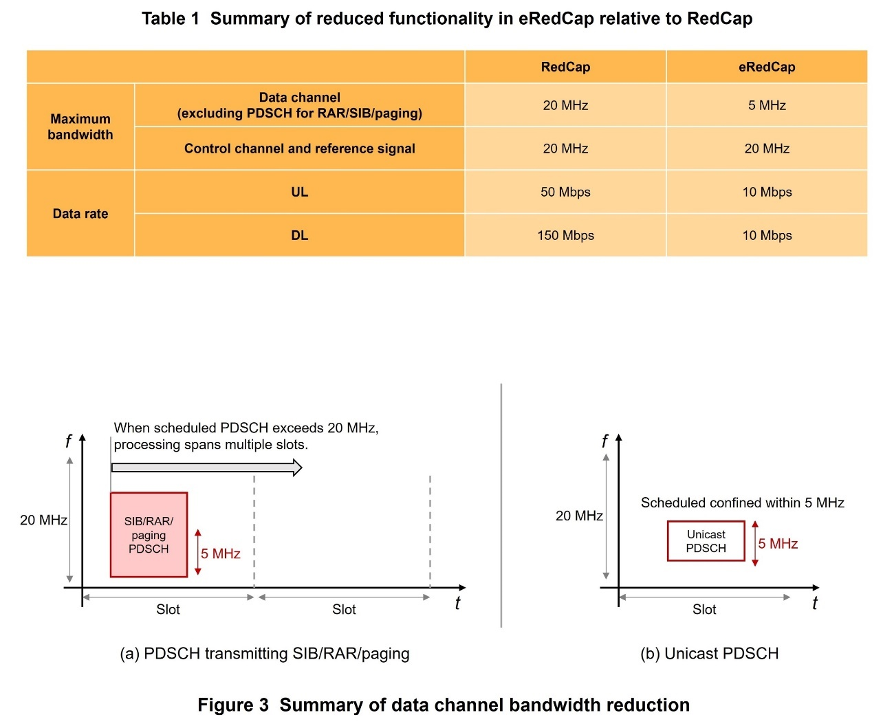
Rel-18 specifies radio technologies for eRedCap UEs which covers a gap in terms of performance and complexity between RedCap, mid-range IoT devices provided by NR, and the eMTC/NB-IoT devices provided by LTE-IoT. An overview of reduced functionality of eRedCap compared to RedCap is shown in Table 1. Note that operating frequencies of eRedCap UEs are expected to be only FR1*26, but they will support the same functionality as RedCap UEs in general except the functions described below. Optimized functionalities for UE positioning which is supported by RedCap and eRedCap UEs have also been specified in Rel-18.
1) Data Channel Bandwidth Reduction
RedCap UEs are able to transmit and receive data channels*27 up to 20 MHz. For eRedCap UEs, this maximum bandwidth is reduced to 5 MHz. Note that 5 MHz here is the baseband*28 bandwidth of a data channel that can be processed per slot*29 while eRedCap UEs still support the same Radio Frequency (RF)*30 bandwidth as RedCap UEs: up to 20 MHz. Thus, when eRedCap UEs are operating in the same cell as non-RedCap and RedCap UEs in particular, data channels can be scheduled with the frequency resources exceeding 5 MHz that are shared with these legacy NR devices, such as Physical Downlink Shared CHannels (PDSCH)*31 that are used to send System Information Blocks (SIB)*32, Random Access Responses (RAR)*33, and paging*34 (Figure 3 (a)). However, considering the requirement on the processing time for Hybrid Automatic Repeat reQuest-ACKnowledgement (HARQ-ACK)*35 feedback, PDSCH scheduled for unicast to a device are restricted not to be scheduled exceeding 5 MHz (Fig. 3 (b)). Note that this baseband bandwidth reduction is only applied to the data channel. This means that synchronization signals*36, broadcast channels*37, control channels, and other reference signals*38 can be transmitted and received with bandwidth up to 20 MHz, the same as RedCap UEs. According to the outcome of a 3GPP study [3], by applying these bandwidth reductions, UE cost and complexity can be reduced up to 9.2% compared to RedCap UEs.
2) Peak Data Rate Reducation
RedCap UEs target data rates of 150 Mbps on the DL and 50 Mbps on the UL. For eRedCap UEs, the peak data rate is reduced to 10 Mbps on both UL and DL. Specifically, for non-RedCap and RedCap UEs, the product of values used to calculate peak data rates, which are the number of Multiple Input Multiple Output (MIMO)*39 layers, the modulation order*40, and the scaling factor*41 must be larger than or equal to 4. However, for eRedCap UEs, the constraint on this product is relaxed to be one of 0.75, 0.8, or 3.2. According to a 3GPP study[3], UE cost and complexity can be reduced up to 5.4%, compared with RedCap UEs, by the peak data rate reduction.
In addition to the above, it has been specified for eRedCap UEs to report itself as eRedCap UE during initial access, so that the network can differentiate the UE from non-RedCap and RedCap UEs. Furthermore, cell access restrictions specific to eRedCap UEs have also been specified.
Additionally, to further reduce UE power consumption, for extended Discontinuous Reception (eDRX)*42 during the standby (RRC_INACTIVE*43) state, the maximum DRX*44 period of 10.24 s in the RRC_INACTIVE state as specified in Rel-17 was extended to 10,485.76 s, which is the same as the maximum period specified in Rel-17 for the RRC_IDLE state.
3) Improved Positioning Accuracy of RedCap and eRedCap UEs
The Positioning Reference Signal (PRS)*45, which is used exclusively for positioning, is transmitted spanning multiple symbols*46 across the entire usable bandwidth. Highly-accurate timing-based positioning is achieved by improving time resolution*47 through combined reception*48. RedCap UEs specified in Rel-17 and eRedCap UEs specified in Rel-18 can use positioning technologies based on the PRS specified in Rel-16 and Rel-17. However, while non-RedCap UEs can measure PRS with bandwidths up to 100 MHz for FR1 and 400 MHz for FR2, the maximum bandwidths of RedCap and eRedCap UEs are reduced to 20 MHz for FR1 and 100 MHz for FR2. This limits the time measurement resolution and degrades the accuracy of timing-based positioning. General commercial environments require horizontal and vertical positioning accuracy of 3 m and industrial environments such as factories require horizontal and vertical positioning accuracy of 1 m and 3 m respectively; however, these requirements are difficult to achieve with existing positioning technologies due to the issue described above.
Rel-18 includes specifications to mitigate this effect on positioning accuracy due to bandwidth reduction for RedCap and eRedCap UEs. Specifically, it virtually measures PRS with wide bandwidth using PRS hopping in the frequency domain. Actually, PRS measured with frequency hopping*49 includes random phase shift*50 in each PRS resource, so the signals cannot be combined as received. It has therefore been specified that the frequency hopping resources can be overlapped when transmitting SRS for positioning and receiving PRS. The receiver can then measure and correct the phase on the overlapped parts, enabling it to combine the signals. Considering the trade-off between phase correction performance and resource efficiency, the amount of overlap can be configured to be 0, 1, 2 or 4 Physical Resource Blocks (PRBs)*51, depending on transmission conditions. To ensure the same bandwidths as non-RedCap UEs with overlapping, i.e., 100 MHz in FR1 and 400 MHz in FR2, frequency hopping with up to six resources can be configured.
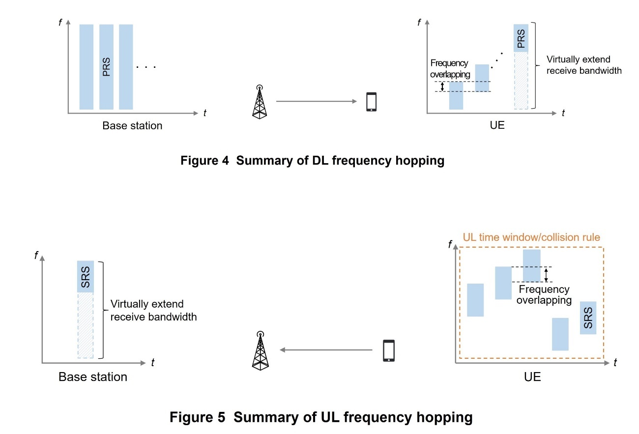
Frequency hopping can be used on the DL when in any of the RRC_CONNECTED*52, RRC_INACTIVE, or RRC_IDLE states. An overview of frequency hopping on the DL is shown in Figure 4. The base station transmits DL PRS with bandwidth up to 100 MHz on FR1 and up to 400 MHz on FR2, the same as to non-RedCap UEs. The UE receives the DL PRS and processes them to combine frequency hopping resources.
Frequency hopping can also be used on the UL, when in either the RRC_CONNECTED or RRC_INACTIVE state. An overview of frequency hopping on the UL is shown in Figure 5. UEs transmit the Sounding Reference Signal (SRS)*53 for positioning with frequency hopping. Base stations receive it and process it to combine frequency-hopping resources. Two rules are specified for behavior if a collision occurs between SRS for positioning with another UL or DL signal or channel during frequency hopping: using a UL time-window to prioritize transmission of SRS for positioning, or a collision rule to prioritize the other signal or channel.
3.2 UAV
For Rel-15 LTE UAV, UAV's altitude reporting, flightpath reporting, and suppression of excessive measurement reporting were specified. For Rel-18 NR UAV, the basic functions of LTE UAV are included, along with further functional extensions. Specifically, these include functions for (1) measurement reporting triggers accounting for altitude, (2) settings for measuring the Synchronization Signals/physical broadcast channel Block (SSB)*54 according to altitude, (3) UAV flight-plan updates, and (4) UAV ID and collision notification.
- 1) For measurement reporting triggers accounting for altitude, new events have been included combining UE altitude information with existing events (Event A3, A4, and A5*55). For example, for the new event called A3H1, a value representing the quality of SpCell is compared with that from a neighbor cell and if the quality of the neighbor cell is offset better than Spcell, and the UAV UE altitude exceeds a threshold, a measurement report is triggered.
- 2) In earlier specifications, the SSB to be measured could be set for each measured frequency during the SSB based RRM Measurement Timing Configuration (SMTC)*56 measurement period, but UAV UEs in the air are able to detect different SSB than UEs on the ground, so for airborne UAV UEs, the SSBs to be measured can now be configured according to altitude.
- 3) For UAV flight-plan reporting updates, thresholds for distance and time-interval to trigger flight-plan updates can be configured. If they are configured, differences in location and timing between the new and earlier flight-plan information can trigger updates if they exceed configured threshold values.
- 4) For UAV ID and collision notification, a function to broadcast the UAV ID on a sidelink, so that the drone regulation body can detect the drone flight (Broadcasting UAV ID (BRID)), and a broadcast function to avoid collisions between UAVs (Detect and Avoid (DAA)) have been introduced.
3.3 Positioning
1) Technologies to Improve Positioning Accuracy
Positioning technologies in NR use a PRS as a reference signal for positioning. Rel-16 and Rel-17 specify positioning methods using the PRS that are timing-based: Time Difference Of Arrival (DL-TDOA)*57, UL-TDOA*58, and Multi-Round Trip Time (RTT)*59; or angle-based: Angle of Departure (DL-AoD)*60 and Angle of Arrival (UL-AoA)*61. Rel-18 specifies features for achieving centimeter-level positioning accuracy: (a) PRS aggregation and (b) Carrier Phase Positioning (CPP).
(a) PRS aggregation
This feature adopts a new measurement method and improves on the accuracy of earlier NR positioning technologies. In Rel-17 and earlier, NR positioning obtained positioning data and computed position per Component Carrier (CC)*62, but did not specify an operation to combine these measurements to obtain a single positioning result. Rel-18 specifies a function that combines wide-band PRS resources (PRS aggregation) to increase frequency resources and increase time resolution. This enables positioning accuracy to be increased, particularly for timing-based methods.
Rel-18 adopted a function that can aggregate PRS from up to three CCs that are intra-band contiguous carriers*63 to compute position. To maximize the increase in positioning accuracy, rather than simply averaging the results of measuring and reporting propagation times, the symbol mapping pattern*64 configurations and aggregation conditions are specified, such as only combining PRS with the same Timing Error Group (TEG)*65 ID, which was introduced in Rel-17. Received power measurement and reporting, such as Reference Signal Received Power (RSRP)*66 and Reference Signal Received Path Power (RSRPP)*67, can now also be averaged over aggregated CCs and reported to the network. The PRS transmission and reception behavior when the PRS of some of the CCs being aggregated collide with other signals is also clarified, including the possibility of stopping transmission of SRS for positioning and continuing measurements with some of the CCs for DL-PRS.
(b) CPP
As discussed above, earlier NR positioning technologies estimate UE position based on differences in arrival time, the round-trip time, or the arrival or departure angle of the PRS. On the other hand, GNSS uses a positioning method that estimates propagation distance between a satellite and the receiver using Carrier Phase (CP)*68, achieving centimeter-level positioning accuracy. Rel-18 adopts CPP to expand applications to include use cases such as IIoT, where highly accurate position is needed indoors where GNSS is weak.
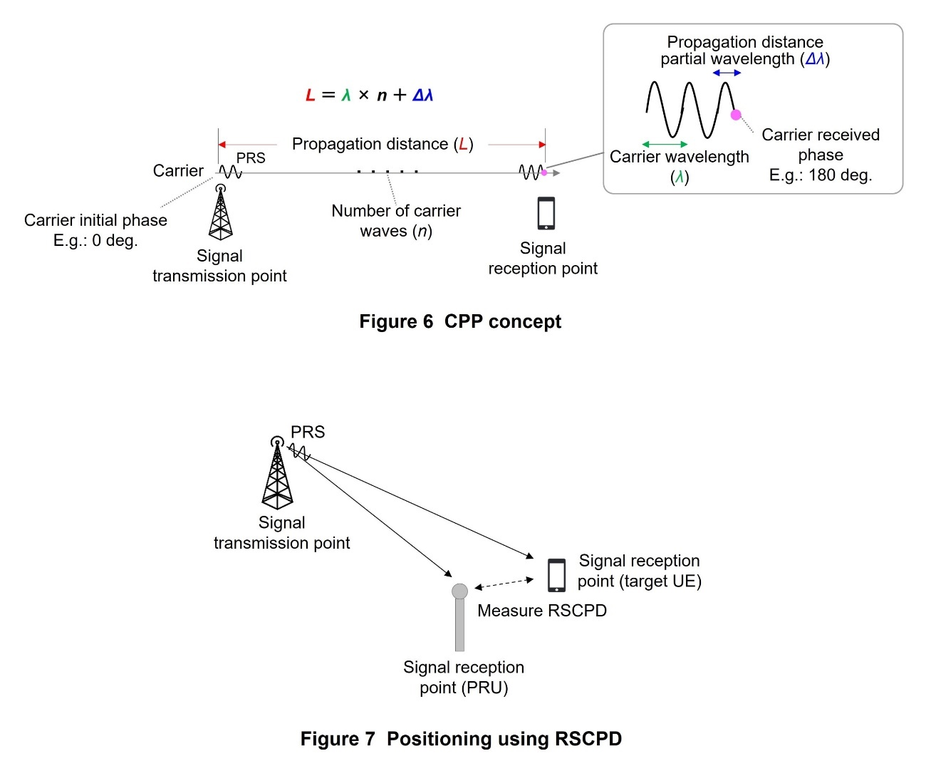
A strength of CPP is the ability to estimate phase difference of the carrier between the signal transmission and reception points to obtain carrier propagation distance and measure position to the centimeter-level (Figure 6). To implement this requires the ability to estimate the propagation distance from the transmission point to the reception point at the carrier wavelength-level, which is called Integer ambiguity resolution*69. Two main approaches to this are assumed for NR.
- The first approach involves using a positioning value from an existing NR positioning technology. Specifically, propagation distance can be approximated using the Rx-Tx time difference*70 at the base station and the UE when using Reference Signal Carrier Phase (RSCP)*71 positioning, and Reference Signal Time Difference (RSTD)*72 or Relative Time of Arrival (RTOA)*73 can be used when using Reference Signal Carrier Phase Difference (RSCPD)*74 positioning, greatly reducing the range of candidates for the amount of carrier phase difference.
- The second approach involves using a Positioning Reference Unit (PRU)*75 to determine the phase measurement. This can be done through RSCPD positioning. For instance, both the UE and the PRU receive the same PRS. Then, by measuring the CP at both the UE and the PRU, we can calculate the difference in the phases that were received. This phase difference helps us figure out where the UE is located in relation to the PRU. The PRU's location is already known accurately (Figure 7).
2) Technologies to Expand the Range of UEs Capable of Positioning
As discussed earlier, the types of UEs other than smartphone, such as RedCap UE and V2X UE, have been expanding recently. NR positioning technology in Rel-18 includes specifications for three types of extended positioning functions, to optimize positioning for these types of UEs: (a) Low Power High Accuracy Positioning (LPHAP), (b) more-accurate positioning on RedCap UE and (c) positioning for sidelink UE. Please see the respective sections for details on these extensions.
3.4 Sidelink
1) Unlicensed Band Support
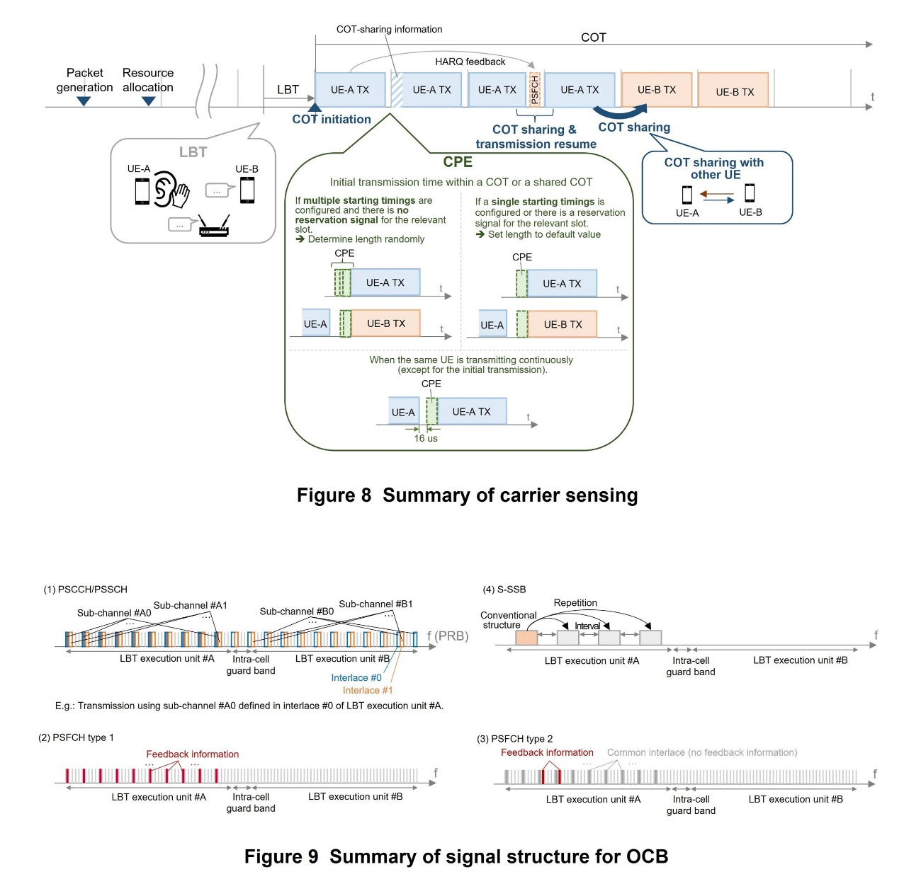
Rel-18 introduces regulations for sidelink communications using the 5 to 6 GHz unlicensed band to increase data rates and expand application areas, and regulations defined by each country or region must be satisfied to use these bands. As with NR Unlicensed (NR-U) specified in Rel-16 [4], Rel-18 sidelink specifications include a Listen Before Talk (LBT)*76 mechanism for carrier sensing*77 and signal structures for Occupied Channel Bandwidth (OCB) requirements*78.
(a) LBT related functions
The LBT mechanism follows that specified for NR-U [4], while a UE initiating a Channel Occupancy Time (COT)*79 can share the COT with other UE, which is a sidelink-dedicated function. Sidelink Control Information (SCI), which is sent together with data transmissions, can include information related to COT sharing and information indicating which UE can use the initiated COT.
The Cyclic Prefix Extension (CPE) function as specified for NR-U is also included, to reduce the time gap between two transmissions from the same or different UE, in order to preserve a COT once it has been acquired. Meanwhile, autonomous resource selection in sidelink may lead to different CPE durations among UEs, and as a result, unnecessary LBT failure. To avoid this situation, CPE duration is determined such that start timing of transmissions is aligned among sidelink UEs if each UE knows that other UE will perform transmission simultaneously.
An overview of the above LBT-related functions is shown in Figure 8. Functions for selecting resources autonomously have also been enhanced, to enable efficient sidelink communications while also performing LBT.
(b) Signal structure for OCB requirements
Regarding the signal structure for OCB requirements, interlaced structures*80 have been introduced for the Physical Sidelink Control CHannel (PSCCH)*81, the Physical Sidelink Shared CHannel (PSSCH)*82, and the Physical Sidelink Feedback CHannel (PSFCH)*83. An overview of the signal structures is shown in Figure 9.
For PSCCH and PSSCH, interlace is associated with sub-channel*84, which is the conventional data-allocation granularity (Fig. 9 (1)).
Two types of interlaced PSFCH structure are specified: Type 1 copies the conventional PSFCH format into the interlace as it is (Fig. 9 (2)), and Type 2 combines a common interlace transmitted to satisfy OCB requirements with one or more specialized PRBs for sending feedback information (Fig. 9 (3)). Type 1 is a simpler, more-reliable structure than Type 2, but Type 2 provides higher PSFCH capacity than Type 1.
The Sidelink Synchronization Signal Block (S-SSB)*85 structure is specified to repeat the conventional signal structure at fixed intervals in the frequency domain (Fig. 9 (4)).
2) Carrier Aggregation
A restricted structure is assumed for the carrier aggregation feature in Rel-18, based on the specific case shown in Fig. 2. The resource allocation mechanism is UE autonomous resource selection, only intra-band carrier aggregation with the same sub-carrier spacing*86 is supported, and UE behavior is defined independently among CCs.
Thus, the following two functions have been specified.
- A function for synchronization between CCs to synchronize entities shared between CCs. S-SSBs for synchronization between UEs are transmitted on a single or multiple CCs, and the method to apply is determined by the UE capabilities.
- A power control function for simultaneous transmission and priority control function when simultaneous transmission occurs. If simultaneous transmission of PSCCH and PSSCH or S-SSB occurs, the priorities of each transmission are compared and the power of the lower-priority transmission is reduced or transmission is cancelled. If multiple PSFCH transmissions occur simultaneously or if PSFCH transmission and PSFCH reception would be performed at the same time, collision handling as performed on a single CC is extended to multiple CCs without modification.
3) Coexistence with LTE Sidelink
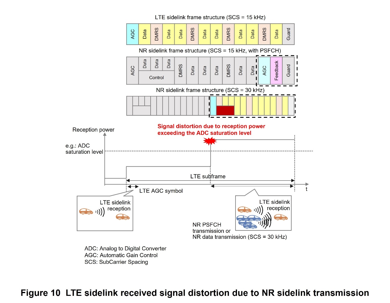
Rel-18 specifications support functions to avoid collision of resources actually used by UEs, considering that available resource candidates for LTE sidelink overlap with those for NR sidelink. It is expected that these functions enable efficient use of LTE sidelink and NR sidelink within the limited bandwidth, as shown in Fig. 2. Specifically, three functions are specified: collision avoidance for when a UE transmits an LTE PSCCH/PSSCH and another UE sends an NR PSCCH/PSSCH, collision avoidance for when a UE sends an LTE PSCCH/PSSCH and the same UE also sends an NR PSCCH/PSSCH, and avoidance of signal distortion that could occur on a receiving UE when NR sidelink transmission begins in the middle of an LTE sidelink subframe*87.
- For the first function, the UE transmitting the NR PSCCH/PSSCH monitors resource reservations on the LTE sidelink and selects NR sidelink resources such that they do not collide with LTE PSCCH/PSSCH transmissions from another UE.
- For the second function, the UE selects NR sidelink resources such that they do not collide with its own transmission reservations on the LTE sidelink.
- For the third function, the relevant NR sidelink transmissions are the PSFCH transmission and a PSCCH/PSSCH transmission for the 30 KHz sub-carrier spacing case, as shown in Figure 10. For either of these transmissions, the power input to the receiver circuit will increase in the middle of the LTE subframe, leading to signal waveform distortion.
To avoid these cases, the UE transmitting the NR PSCCH/PSSCH monitors resource reservations on the LTE sidelink and determines the NR PSCCH/PSSCH resources such that the NR PSFCH resource will not collide with LTE PSCCH/PSSCH transmissions from another UE. The UE transmitting the NR PSCCH/PSSCH also monitors LTE sidelink resource reservations and behaves such that it does not increase transmission power in the middle of transmission of a PSCCH/PSSCH by another UE on the LTE sidelink.
4) Positioning Support for Sidelink UE
For NR, sidelink functions for communications between UEs have been specified since Rel-16, but there has not been a specification for positioning technology using sidelink. Recently, there has also been demand on sidelink positioning from the wider market, not just for V2X, so specifications for sidelink positioning have been added based on the NR positioning technologies specified to Rel-17.
A new reference signal used for sidelink positioning has been specified, called the SideLink-Positioning Reference Signal (SL-PRS). UEs transmit the SL-PRS to each other, obtain parameters such as TDOA, RTT, and AoA, and calculate their positions.
In NR, resources used for sidelink communications are defined as Resource Pools (RP)*88, and a RP is similarly specified for SL-PRS, used for sidelink positioning. In particular, two types of RPs are specified: shared RP, with resources that can be allocated with flexibility for data signals or SL-PRS, and dedicated RP, with wide-band resources to be used only for SL-PRS.
To allocate resources for transmitting SL-PRS, as with allocating resources for communications, two modes are defined: one in which SL-PRS resources are scheduled by the network, and one in which sidelink UE can decide SL-PRS resources autonomously. Similar to DL-PRS, the SL-PRS signal structure uses comb mapping patterns*89. Specifications support comb sizes*90 of 1, 2, 4, and 6 and structures with from 1 to 9 symbols, and available patterns differ depending on the RP type.
3.5 Industrial IoT
1) Time Resiliency
Rel-16 and 17 specified time synchronization functions using 5G for industrial IoT. Rel-18 has introduced time-synchronization status monitoring functions, considering that the accuracy of time synchronization could degrade.
The method for monitoring time synchronization status differs depending on whether the UE is in the RRC_CONNECTED or RRC_IDLE/INACTIVE state. Specifically, a UE in the RRC_CONNECTED state directly receives clock quality information sent from the base station in an RRC message. Clock quality information includes (1) a clock quality metric*91 and (2) a base station time synchronization status.
- 1) The clock quality metric can configure one or more parameters representing time synchronization state, including clock accuracy*92, traceability to Coordinated Universal Time (UTC)*93, traceability to GNSS*94, frequency stability*95, parent time source*96, and synchronization state*97.
- 2) Base station time synchronization status is a parameter that indicates whether the base station clock quality satisfies the synchronization accuracy index from the Access and Mobility management Function (AMF)*98 or not. If it is not satisfied, application services can be temporarily suspended to avoid errors due to the degraded time synchronization accuracy.
If time has elapsed since the previous synchronization, resynchronization will be necessary, but the UE may have dropped into an RRC_IDLE/INACTIVE state. For UE in the RRC_IDLE/INACTIVE state, a function has been introduced to notify whether the clock quality data in the system information from the base station has been updated. A UE that receives notification that the clock quality information has updated can move to the RRC_CONNECTED state and then the clock quality information will be sent from the base station.
2) LPHAP Support
Generally, sensors and other UEs used in a factory are not expected to be recharged or have battery changes often, so they require positioning that conserves battery power consumption. As shown by use case #6 in TS 22.104 [5], low-power positioning is specified, targeting horizontal positioning accuracy within 1 m with positioning interval of 15 to 30 s, and battery life of 6 to 12 months.
UEs in the RRC_INACTIVE state require a transition to the RRC_CONNECTED state for reconfiguration of SRS for positioning each time the UE moves between cells, and this frequent state changing causes an issue for low-power positioning. To continue low-power positioning, even when moving between cells, the SRS for positioning configuration has been made common within multi-cell areas called validity areas. Note that the three aspects: (1) UL transmission timing, (2) UL beam spatial relation*99, and (3) UL transmission power control; do not share a common configuration within the validity area, but the following UE behavior is specified for them, without transition to the RRC_CONNECTED state.
- 1) For UL transmission timing, the UE default behavior is to maintain the transmission timing of the last serving cell*100 in the validity area. Alternatively, if the UE has the capability, it can discard the previously used transmission timing and adjust the timing autonomously when it selects another cell if configured by the network.
- 2) For the UL beam spatial relation, the network can preconfigure reference signal information used to decide the beam used to transmit SRS for positioning. In this case, the UE uses a pre-configured DL reference signal to determine the UL beam. However, if the configured reference signal cannot be accurately measured, the UE suspends UL transmission and waits until the reference signal is accurately measured.
If the reference signal information is not preconfigured by the network, the UE uses a fixed beam or a different beam for each SRS resource. - 3) For UL transmission power control, if the path loss reference signal is provided in the configuration, the UE uses the specified DL reference signal to determine the UL transmission power.
If the path loss reference signal is not provided in the configuration or accurate measurements cannot be taken, the UE calculates the UL transmission power from an SSB retrieved from a Master Information Block (MIB)*101
Other extensions for reducing UE power consumption include increasing the maximum period for transmitting the SRS for positioning from 10,240 ms to 20,480 ms, and expanding measurement of RSTD, RSRP, and RSRPP using the DL-PRS for the RRC_IDLE state.
3.6 NTN
As in Rel-17, Rel-18 also includes consideration for NTN, which are anticipated to provide new network coverage for areas such as in the air, at sea and in mountainous areas, using relay stations such as GEostationary Orbit (GEO) and LEO satellites and aircraft, including High Altitude Platform Station (HAPS)*102 flying in the stratosphere, for GNSS-equipped UEs such as VSAT UEs, and compact devices including smartphones.
1) UL Coverage Improvement
As mentioned above, UL channels that do not satisfy the required communication quality were evaluated assuming devices such as smartphones, and based on the evaluation results, NTN specifications have been enhanced for: (1) Support for repeated transmission of the Physical Uplink Control CHannel (PUCCH)*103 used for initial access and (2) NTN-specific mechanism of the DeModulation Reference Signal (DMRS)*104 bundling function on the Physical Uplink Shared CHannel (PUSCH)*105.
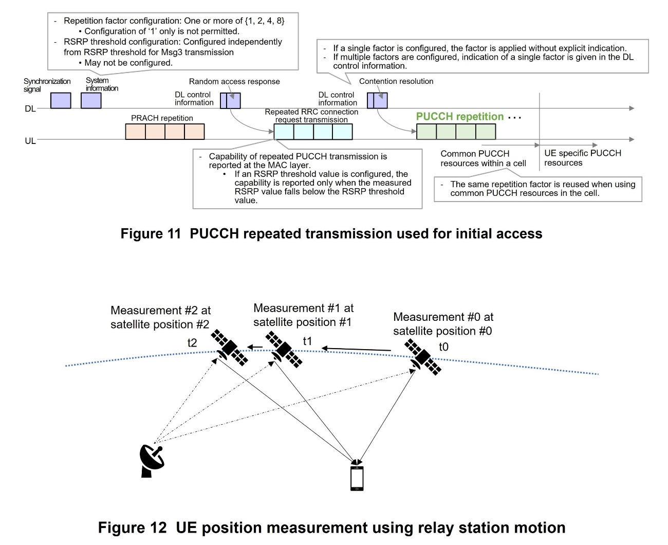
- (1) Regarding repeated transmission on the PUCCH used for initial access, UE is provided with repeated transmission through the system information that is common within the cell, and UE capable of performing PUCCH repetition for initial access determines whether to perform the repetition and the number of repetitions, based on the signal reception strength and indication from the network. The network receives reports via the PUSCH transmitted before the PUCCH in the initial access, on whether each UE is capable of performing PUCCH repetition for initial access. This operation is shown in Figure 11.
- (2) The enhancement of the DMRS bundling function on PUSCH for NTN is based on the DMRS bundling function for PUSCH specified in Rel-17, and this function improves reception quality (i.e. coverage performance) by enabling channel estimation*106 over multiple slots.
To apply channel estimation across multiple slots, it is necessary to maintain phase continuity and power consistency of PUSCH and confine phase variation to a certain amount or less, within the transmission duration. However, with NTN, especially in cases where relay stations such as LEO are moving, there will be significant phase rotation due to the movement of the relay station. Thus, for the phase rotations specific to NTN, it is assumed that UE will perform a pre-compensation operation and transmit PUSCH while performing this compensation. UEs capable of performing the pre-compensation operation report this capability to the network.
2) NW Verified UE Location
A mechanism for NTN to verify UE location has been introduced based on the existing specification for UE positioning supported for Terrestrial Networks (TN). In TN, UE location is calculated from results of transmitting and receiving signals between the UE and multiple base stations, but in NTN, it is mainly the case that signals are transmitted and received only between the UE and a single relay station. As such, the location verification is realized by performing several measurements at different times, utilizing the movement of relay stations such as LEO. An outline is shown in Figure 12.
The Multi-RTT method is used as the UE location verification function, and the base station and UE perform NTN-specific measurement and reporting functions (e.g.: reporting DL timing drift, the feeder link*107 and satellite orbit information) related to the large latency, special synchronization methods, etc.
3) Extensions for Mobility between NTN and TN and between NTN and NTN
For mobility between NTN and TN, to avoid measurement of TN frequencies when a UE is in the RRC_IDLE or RRC_INACTIVE state, which are not needed by UE in a NTN cell, a function has been added to broadcast the TN physical coverage for each frequency in the SIB. TN physical coverage is expressed as a circle defined by a reference location and a radius. UEs located in an NTN cell only measure TN frequencies when they are in a location with TN physical coverage. This can be expected to reduce UE power consumption.
For mobility between NTN and NTN, a function called RACH-less handover has been introduced. For NTN cells that have an earth moving cell structure in particular, coverage moves relative to the ground, so periodically, all UEs within the cell must go through handover at once. The number of UEs handled by an NTN cell can be very high, so if they all transmit the random access signal at once, the UL transmission overhead could become an issue. If the target cell Timing Advance (TA)*108 value for the RACH-less handover function is zero or the same as the source cell, the UE can access it directly, without performing random access. To enable the UE to send the first UL data to the target cell, the base station configures a configured grant*109 PUSCH resource beforehand. A UE may also send the first UL data to the target cell using a dynamic grant*110 PUSCH resource.
4) Frequency Band Support for VSAT UEs
17.3-20.2 GHz for DL and 27.5-30.0 GHz for UL have been designated as frequencies for NTN and defined as FR2-NTN, and the wireless performance regulations and test specifications for UEs and base stations were formulated mainly, to make these frequency bands available for VSAT UEs. Also, cell search follows the FR2 specifications, and the scheduling timing offset and reporting of TA follow the same mechanisms as in the NTN specifications for FR1.
For Physical Random Access CHannel (PRACH)*111 configuration, the FR2 specifications for Time Division Duplex (TDD) *112 will also be used for FR2-NTN, which is a Frequency Division Duplex (FDD) *113 band.
- FR1: Refers to the 450-6,000 MHz frequency band.
- Data channels: A general term for physical channels used to transmit data, such as PDSCH (see *31) and PUSCH (see *105).
- Baseband: The signal band before modulation to and after demodulation from the carrier frequency of a radio signal.
- Slot: Unit for scheduling data, consisting of multiple Orthogonal Frequency Division Multiplexing (OFDM) symbols.
- RF: Signal or radio wave of frequency used as a carrier for radio communications.
- PDSCH: The physical channel used to transmit data packets on the DL.
- SIB: System information that is broadcast by a base station to all UEs, partitioned into radio blocks that are referred to as SIB.
- RAR: During random access, information including a temporary UE identifier and resource-allocation to be used thereafter for random access, which the base station sends in response after detecting a preamble sent by a UE.
- Paging: Incoming call notification sent to a UE in standby within a cell.
- HARQ-ACK: A signal acknowledges that the node received and decoded the data correctly.
- Synchronization signal: A physical signal that enables detection of the synchronization source identifiers (cell ID, etc.), and frequency and reception timing required for the mobile terminal to start communications.
- Broadcast channel: Shared channel for broadcasting system operation information. A mobile UE reads this channel on powering up to obtain information such as operator code, shared channel structure, and adjacent cell information, which is needed to begin communications.
- Reference signal: A known signal configured in the UE by the base station.
- MIMO: A signal transmission technology that uses multiple antennas for transmission and reception to improve communications quality and frequency utilization efficiency.
- Modulation order: The number of signal phase-amplitude points in data modulation. This number is 4 in Quadrature Phase Shift Keying (QPSK) and 16 in 16 Quadrature Amplitude Modulation (16QAM).
- Scaling factor: A value of 0.4, 0.75, 0.8 or 1, selected according to the UE baseband processing capabilities. Higher values indicate higher baseband processing performance per unit time.
- eDRX: Extended DRX cycle when performing DRX (see *44).
- RRC_INACTIVE: A UE state in RRC where the UE does not have cell-level identification within the base station and where the context of the UE is held in both the base station and the core network.
- DRX: Intermittent reception control, to reduce UE power consumption.
- PRS: A reference signal specifically for positioning. For positioning, the DL-PRS is specified on the DL signal, and the SRS is specified on the UL signal.
- Symbol: A time unit of transmitted data consisting of multiple subcarriers in OFDM. Multiple bits are mapped to each subcarrier (e.g., 2 bits in QPSK).
- Time resolution: For timing-based positioning, the distance between UE and base station is estimated based on measurement of the propagation time of a reference signal. This term refers to the resolution/granularity of that measurement.
- Combined reception: A method to obtain a single measured result by combining signals received by the receiving device.
- Frequency hopping: A transmission method using a different frequency or frequency resource for each transmission.
- Random phase shift: A random phase shift in the RF occurring when the transmission/reception frequency is switched, produced by differences in phase change during propagation due to the different frequencies and other causes.
- PRB: A unit for allocating radio resources, consisting of one subframe and 12 subcarriers.
- RRC_CONNECTED: An RRC state of UE when the UE has a cell-level identifier in the base station, and the UE context is stored in both the base station and the core network.
- SRS: A reference signal used to measure UL channel quality, reception timing, etc. at the base station.
- SSB: A synchronization signal transmitted periodically by base stations so that UE can detect cell frequencies and reception timing, which are needed for communications.
- Event A3, A4, A5: Events that trigger quality measurement reports during handover. Event A3 triggers a quality measurement report when the quality in a neighboring cell is better by an offset. Event A4 triggers a quality measurement report when the quality in a neighboring cell exceeds a threshold. Event A5 triggers a quality measurement report when the quality in the current cell is worse than threshold1 and the quality in the neighboring cell is better than threshold2.
- SMTC: Refers to measurement timing start, interval, and period when a UE measures reception quality using the SSB.
- DL-TDOA: A positioning technology that estimates UE position by transmitting DL reference signals to the UE from multiple base stations simultaneously and using differences in the arrival times of those signals together with the coordinates of each base station.
- UL-TDOA: A positioning technology that estimates UE position by transmitting a UL reference signal from the UE to multiple surrounding base stations and using differences in the arrival times of those signals together with the coordinates of each base station.
- Multi-RTT: A positioning technology that estimates UE position based on the RTTs between the UE and multiple base stations together with the coordinates of each base station.
- DL-AoD: A positioning technology that estimates UE position by transmitting a DL reference signal from the base station to the UE and using the index and received strength of the received beam and the beam's horizontal and vertical angles of departure at the base station.
- UL-AoA: A positioning technology that estimates UE position by transmitting a UL reference signal from the UE to the base station and using the horizontal and vertical angles of arrival.
- CC: A term used to indicate one of the carriers in carrier aggregation.
- Intra-band contiguous carriers: A scenario in which communication is done using multiple contiguous carriers in the same frequency band.
- Symbol mapping pattern: An arrangement of time and frequency resources specified beforehand in the specifications.
- TEG: A feature for reducing degradation of positioning accuracy. Refers to grouping of antenna panels or antenna elements when the latency of processing for converting the digital signal to analog (or vice-versa) is below a fixed value.
- RSRP: Received power level of a reference signal measured by the UE. RSRP is an indicator of receiver sensitivity of a mobile terminal.
- RSRPP: The reception level for each path of a reference signal, measured by a UE. An index expressing the reception sensitivity of a UE.
- CP: The phase of an NR carrier, expressed as an angle from 0 to 360 degrees.
- Integer ambiguity resolution: The process for computing the propagation distance between the signal transmission point and reception point using the carrier phase. There are various methods, such as using propagation of several different frequencies, as with GNSS, or utilizing the movement of a satellite and taking multiple measurements at different times.
- Rx-Tx time difference: The difference between transmission and reception time for a signal.
- RSCP: Received-carrier phase value. To increase positioning accuracy, Rel-18 has regulations for both DL and UL. In Rel-18, this is used together with the positioning value obtained using an existing NR positioning technology.
- RSTD: The relative reception time difference between two Transmission Points (TP), usually measured by a UE.
- RTOA: The relative reception time difference between two Reception Points (RP), usually measured at a TRP.
- RSCPD: The measurable carrier phase difference when a UE receives DL-PRS sent simultaneously from multiple TRPs. In Rel-18, this is used together with measurements obtained using existing NR positioning technology.
- PRU: Equipment whose location data is known to the network and is used to assist in calculating position of nearby UE. It provides functions to receive DL-PRS and report positioning results to the network, and to transmit SRS for positioning to TRPs.
- LBT: A mechanism by which a device checks whether another device is transmitting data by radio before transmitting data itself.
- Carrier sensing: A technology that checks that a carrier frequency is not in use for other communication before starting transmission.
- OCB requirements: A regulation that requires the band containing 99% of the signal power to occupy 80 to 100% of the transmission band.
- COT: For unlicensed bands, the time period over which a base station or UE exclusively uses the band for transmitting and receiving data.
- Interlacing structure: A structure that handles fixed-interval PRBs as one block.
- PSCCH: A physical channel used to send and receive control information regarding PSSCH (see *82) reception and resource reservation on the sidelink.
- PSSCH: A physical channel used to send and receive data packets and some control information on the sidelink.
- PSFCH: A physical channel used to send and receive feedback control information such as confirmations of PSSCH reception on the sidelink.
- Sub-channel: A resource unit consisting of multiple PRBs. Resource allocation is performed in sub-channel units on the sidelink.
- S-SSB: A synchronization signal block transmitted on the sidelink for synchronization between UEs.
- Subcarrier spacing: The interval between individual carriers used to transmit signals in multi-carrier transmission such as OFDM.
- Subframe: A unit of time-domain radio resources composed of multiple OFDM symbols (in LTE, 14 OFDM symbols).
- RP: A term for time and frequency resources that can be used by sidelink. Communications parameters, resource configuration, and resource allocation are done with RPs.
- Comb mapping pattern: A mapping method in which signal resources are arranged so that symbols are not consecutive on the same sub-carrier.
- Comb size: The signal arrangement interval in a comb mapping pattern.
- Metric: A system for measuring and quantifying an attribute or state of something based on a fixed standard.
- Clock accuracy: Indicates the difference between measured time and a reference clock. Units are ns.
- Traceability to UTC: Expresses whether the current time source can be traced to UTC.
- Traceability to GNSS: Expresses whether the current time source can be traced to GNSS.
- Frequency stability: Estimates the amount of variation in the local clock when it is not being synchronized with another time source.
- Parent time source: Represents the main time source being used by the current node. Can be set to any of “SyncE”, “PTP”, “GNSS”, “atomic clock”, “terrestrial radio”, “serial time code”, “NTP”, “hand_set”, or “other”.
- Synchronization state: Represents the synchronization state of the node. It can be set to modes defined in ITU T G.810, which are “Locked”, “Holdover”, and “Freerun”.
- AMF: Logical node that houses the base station (gNB) and provides mobility control, etc. in the 5G core network.
- UL beam spatial relation: Information specifying the UE beam being used for the PUCCH (see*103), SRS, etc. for UL transmission.
- Serving cell: The cell to which a UE currently has an established radio link.
- MIB: After a UE has performed a cell search, this is the first notification signal that it must read, containing the bare minimum information needed.
- HAPS: An aircraft positioned in the stratosphere, roughly 20 km above the Earth's surface and appearing from the ground to be stationary or circling. Anticipated to be used for communications, similar to communications satellites. Since HAPSs are at relatively low altitude, they will provide benefits of low latency, with one-way propagation times near 0.1 ms, and easy direct communications with UE.
- PUCCH: Physical channel used for sending and receiving control signals in the UL.
- DMRS: Reference signal used for channel sounding when demodulating a transmitted signal.
- PUSCH: Shared physical channel used for sending and receiving data on the UL.
- Channel estimation: Estimation of changes in parameters such as amplitude and phase as a signal traverses a radio channel.
- Feeder link: In an NTN, the radio link connecting the ground station to the aircraft.
- TA: The difference between the desired UL signal reception timing on the UE and the actual UL reception timing.
- Configured grant: A mechanism for allocating PUSCH resources beforehand from the base station on a user-by-user basis so that UE can transmit PUSCH by those resources if UL data is generated without having to transmit a Scheduling Request (SR).
- Dynamic grant: A mechanism by which the UE requests scheduling, and the base station sends DCI and allocates a transmission resource for UL data.
- PRACH: The physical channel that a UE uses for its initial transmission during the random access procedure.
- TDD: A signal transmission method in which the same carrier frequency or frequency band is partitioned into time slots used for UL and DL.
- FDD: A method for implementing simultaneous transmission and reception with radio communications etc, in which transmission and reception are done using different frequencies.
-
This article has described radio technologies for ...
Open
This article has described radio technologies for industry-collaboration solutions as specified in Rel-18. Study of NTN technical expansion and technologies for ambient IoT, in which communications will operate using energy from the surrounding environment as with Radio Frequency IDentification (RFID)*114, is ongoing for Rel-19, and specifications aiming for further industry-collaboration solutions are expected to be developed. NTT DOCOMO will continue contributing to industry-collaboration solutions as 5G develops further and into the 6G era.
- RFID: A scheme for wirelessly obtaining ID information embedded in small IC chips to identify and manage people and objects.
-
REFERENCES
Open
- [1] S. Kumamagai et al.: “Advanced Technologies for Industry Creation and Solution Co-creation in 3GPP Release 17,” NTT DOCOMO Technical Journal, Vol. 24, No. 3, Jan. 2023.
https://www.docomo.ne.jp/english/corporate/technology/rd/technical_journal/bn/vol24_3/001.html - [2] K. Aoyagi et al.: “5G Advanced Technologies for Creating Industries and Co-creating Solutions,” NTT DOCOMO Technical Journal, Vol. 22, No. 3, pp. 71-89, Jan. 2021.
 https://www.docomo.ne.jp/english/binary/pdf/corporate/technology/rd/technical_journal/bn/vol22_3/vol22_3_008en.pdf (PDF format:2,081KB)
 - [3] 3GPP TR38.865 V18.0.0: “Study on further NR RedCap UE complexity reduction,” Sep. 2022.
- [4] Y. Matsumura et al.: “5G Advanced Technologies for Mobile Broadband,” NTT DOCOMO Technical Journal, Vol. 22, No. 3, pp. 90-105, Jan. 2021.
https://www.docomo.ne.jp/english/binary/pdf/corporate/technology/rd/technical_journal/bn/vol22_3/vol22_3_009en.pdf (PDF format:1,895KB) - [5] 3GPP TR22.104 V18.3.0: “Service requirements for cyber-physical control applications in vertical domains,” Dec. 2021.
- [1] S. Kumamagai et al.: “Advanced Technologies for Industry Creation and Solution Co-creation in 3GPP Release 17,” NTT DOCOMO Technical Journal, Vol. 24, No. 3, Jan. 2023.

