
Special Articles on 3GPP Release 18 Standardization Activities (1)
Enhanced Mobile Broadband Technologies in 3GPP Release 18
eMBB High Throughput and High Capacity 5G NR
Yuki Matsumura, Naoya Shibaike and Mamoru Okumura
6G Network Innovation Department
Riki Okawa and Koki Yamashita
Radio Access Network Technology Promotion Office
Yuta Oguma and Ryu Kitagawa
Device-Tech Development Department
Abstract
In March 2020, NTT DOCOMO began 5G services using the 3GPP Release 15 standard. 5G services will proliferate from here on, and further improvements in wireless network throughput, capacity, and coverage will be demanded. Toward this end, 3GPP established the Release 18 standard in June 2024. This release expands and enhances the specifications of Releases 15 to 17. This article describes the technologies to improve throughput, capacity, and coverage in the radio access specifications in Release 18.
01. Introduction
-
In March 2020, NTT DOCOMO began 5th Generation mobile communications ...
Open

In March 2020, NTT DOCOMO began 5th Generation mobile communications system (5G) services using New Radio (NR)*1 as standardized in the 3rd Generation Partnership Project (3GPP) Release 15 (Rel-15). Rel-15 makes possible a variety of 5G services thanks to capabilities such as high throughput, high capacity, high reliability and low latency, and massive device connectivity. However, as services proliferate, further enhancements and improvements of wireless communication network capabilities are needed. In response, 3GPP released Rel-18 in June 2024. Rel-18 expands and enhances the functionalities of Rel-15-17 [1]-[3].
In this article we describe the functions in 3GPP Rel-18 for increasing throughput and capacity to achieve enhanced Mobile BroadBand (eMBB)*2 as well as functions for enhancing coverage*3 to expand the application range of 5G NR.
As functionalities for increasing throughput and capacity, we explain advanced Multiple Input Multiple Output (MIMO)*4, which seeks to increase system capacity and user throughput; enhanced handover*5 to reduce latency and increase flexibility; enhanced Extended Reality (XR)*6 technologies aimed at achieving low latency and high capacity in XR scenarios; enhanced multi-carrier technology to improve throughput in multi-carrier operation; and enhanced User Equipment (UE)*7 Radio Frequency (RF)*8 technologies for Frequency Range 1 (FR1)*9 and Frequency Range 2 (FR2)*10 to increase user throughput.
As functionalities for expanding coverage, we explain the following technologies: Physical Random Access CHannel (PRACH)*11 repetitions for the physical channel*12 to enhance PRACH coverage, methods for improving UpLink (UL)*13 transmission power efficiency, and dynamic waveform*14 switching to prevent resetting of Radio Resource Control (RRC)*15 when switching waveform in the UL.
- NR: Radio system standard formulated for 5G. Compared with 4G, NR enables high-data-rate and high-capacity communications using high frequency bands (e.g. 3.7 GHz, 4.5 GHz, 28 GHz bands), and low-latency and high-reliability communications for achieving advanced IoT.
- eMBB: Generic name for communications requiring high data rates and large capacity.
- Coverage: The area (cell radius) in which communications with UEs (see *7) per base station can be carried out. The greater the coverage, the fewer the number of base stations to be installed.
- MIMO: A signaling technique whereby multiple transmit and receive antennas are used to transmit signals simultaneously and at the same frequency to improve communications quality and the efficiency of frequency utilization.
- Handover: Switching of the serving cell (see *61) to which the UE is connected.
- XR: Generic name for technology that provides new experiences by merging real space and virtual space using wearable terminals, etc.
- UE: A mobile device having functions conforming to 3GPP.
- RF: Refers to the radio frequency analog circuit.
- FR1: A frequency range of 450-7,125 MHz.
- FR2: Frequency range from 24.25 to 71.0 GHz. In Rel-15, FR2 is defined as 24.25 to 52.6 GHz. Rel-17 extended the upper limit from 52.6 GHz to 71.0 GHz. The previous FR2 band (24.25 to 52.6 GHz) is defined as FR2-1 while the expanded FR2 band (52.6 to 71.0 GHz) is defined as FR2-2.
- PRACH: Physical channel for transmission when the UE establishes a connection with a cell, for example, for initial access or handover.
- Physical channel: A generic term for channels that are mapped onto physical resources such as frequency or time, and transmit control information and other higher layer data.
- UL: The flow of information from UEs to the base station.
- Waveform: Transmission waveform used during signal transmission.
- RRC: Layer 3 protocol that controls radio resources on the radio network.
-
2.1 Enhancing MIMO to Improve System Capacity and User Throughput
Open
1) Improving System Capacity by Increasing Maximum Number of Users in Multi-User MIMO (MU-MIMO)*16
In Rel-15 to Rel-17, high throughput and high capacity are achieved for the Physical Downlink Shared CHannel (PDSCH)*17 and the Physical Uplink Shared CHannel (PUSCH)*18 using Spatial Domain Multiplexing (SDM)*19, which is based on MIMO technology. Each MIMO layer*20 of PDSCH/PUSCH has a DeModulation Reference Signal (DMRS)*21. Because different DMRS ports*22 are allocated to each MIMO layer, the total number of MIMO layers within a UE and between UEs for Single User MIMO (SU-MIMO)*23 and MU-MIMO is limited by the number of maximum DMRS ports supported by specification. In Rel-15 to Rel-17, a maximum of 8 ports is specified for DMRS Type1*24 and a maximum of 12 ports for DMRS Type2. For example, by using 12 DMRS ports, in the case of 4-layer SU-MIMO for one UE, three UEs can simultaneously send and receive data with MU-MIMO by SDM.
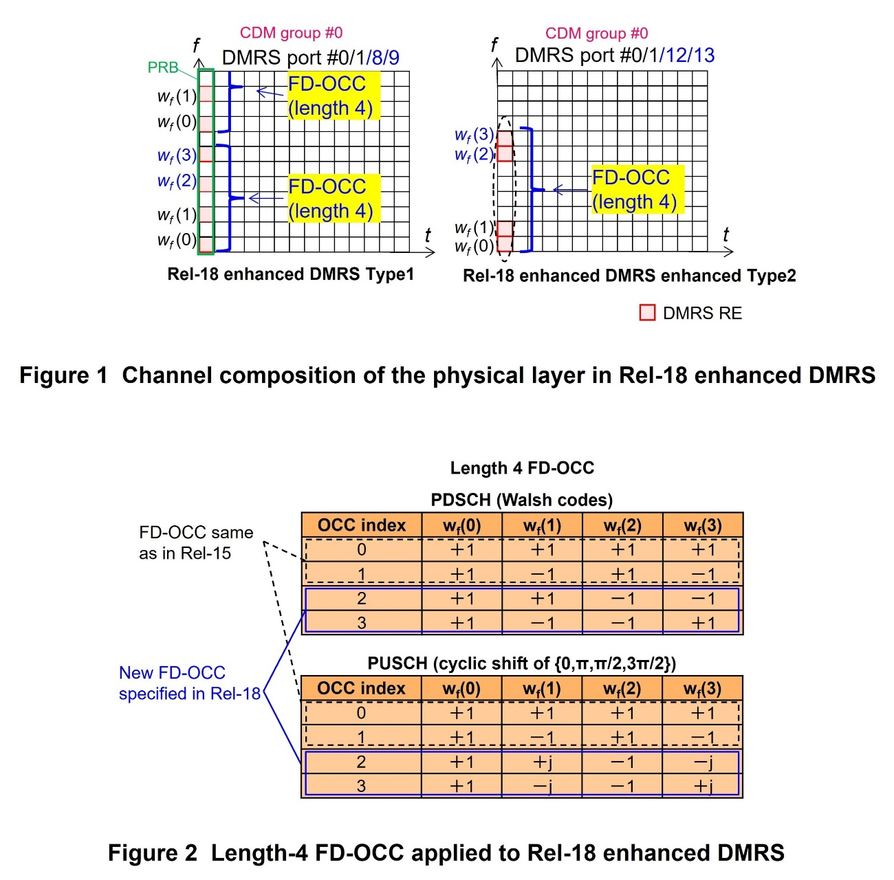
In Rel-18, to double the system capacity of MU-MIMO, enhanced DMRS is specified for PDSCH and PUSCH. Enhanced DMRS doubles the number of maximum DMRS ports up to Rel-17 for DMRS Type1 and DMRS Type2. Also, by increasing code domain multiplexing, time-frequency domain multiplexing can be decreased as a result, allowing SU-MIMO to be carried out with fewer physical DMRS resources. Compared with releases up to Rel-17, the DMRS overhead*25 of PDSCH/PUSCH can be reduced and user throughput can be increased. Specifically, the length of Frequency Domain Orthogonal Code (FD-OCC)*26, which is 2 symbols up to Rel-17, is extended to 4 in Rel-18. The maximum number of DMRS ports is thus doubled from up to Rel-17.
The channel mapping of the Rel-18 enhanced DMRS in the physical layer*27 , with CDM group*28 #0 as an example, is shown in Figure 1. Length-4 FD-OCC applied to enhanced DMRS in Rel-18 is shown in Figure 2. In Rel-18 enhanced DMRS, length-4 FD-OCC is applied to four adjacent Physical Resource Elements (PREs)*29 in the same CDM group in the same or adjacent Physical Resource Block (PRB)*30. Length-4 FD-OCC for PDSCH is generated by Walsh codes*31. Length-4 FD-OCC for PUSCH is generated by cyclic shift*32 with phase = {0, π, π/2, 3π/2}. For both PDSCH and PUSCH, DMRS ports #0 and #1, which use FD-OCC index = {0,1} in Rel-18 enhanced DMRS, are designed so they have the same channel configuration as DMRS ports #0 and #1 in releases up to Rel-17, which also use FD-OCC index = {0,1}. In the Rel-18 enhanced DMRS, FD-OCC adopted in Rel-18 is applied to DMRS ports #8 and #9 (in the case of enhanced Type 1) and DMRS ports #12 and #13 (in the case of enhanced Type 2), which all use FD-OCC index = {2,3}.
In Rel-18 enhanced Type1 DMRS, FD-OCC is applied to four adjacent PREs of the six PREs corresponding to the same CDM group within a PRB (the bottom four red blocks in Rel-18 enhanced Type 1 DMRS, shown on the left side of Fig. 1). Two PREs thus remain (the top two red blocks in Rel-18 enhanced Type 1 DMRS in Fig. 1). Therefore, two adjacent REs in the same CDM group in the adjacent PRB are used, and length-4 FD-OCC is applied between adjacent PRBs. Because of this, basic UEs without advanced UE capability*33 must simultaneously receive adjacent PREs in two PRBs. They thus require constraints in base station scheduling, such as the number of scheduled PDSCH PRBs being even. On the other hand, UEs with advanced UE capability can receive and transmit PDSCH even without adjacent PRE on one side, so there are no scheduling constraints in the allocation of base station PDSCH resources.
2) Improving UL User Throughput through Simultaneous Transmission with Multi-Panel (STxMP)
Rel-16/17 specified Multi-Transmission and Reception Point (TRP)*34 scenarios in which base stations transmit and receive signals using two TRPs in different locations. In DownLink (DL)*35 multi-TRP scenarios, multiple TRPs transmit signals simultaneously using different DL transmission beams. This has the effect of increasing DL throughput by effectively increasing the number of MIMO layers or by improving reliability through repetitions.
In Rel-18, functions are specified for a UE's two transmission panels to each simultaneously transmit signals using different UL transmission beams. Like DL Multi-TRP, this also has the effect of increasing UL throughput by effectively increasing the number of MIMO layers or improving reliability through repetitions.
For multiple TRPs to coordinate and schedule the UE's PUSCH or Physical Uplink Control CHannel (PUCCH)*36, it is necessary to exchange control information such as the availability of time-frequency domain resources between TRPs. Specified are functions that assume an ideal backhaul*37 environment, in which high-capacity, low-latency backhaul circuits are installed and low-latency exchanges of control information between TRPs take place; and functions that assume a non-ideal backhaul environment without low latency.
(1) Single Downlink Control Information (DCI)*38 functions for ideal backhaul environment
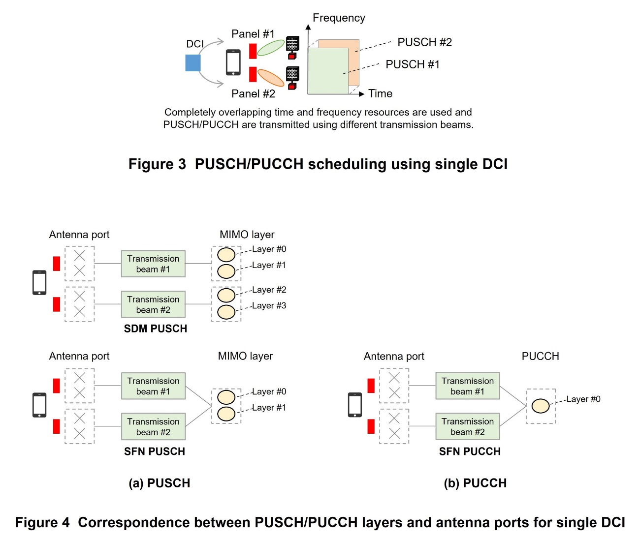
In the case of an ideal backhaul environment, two TRPs can coordinate to schedule the PUSCH or PUCCH of the UE. As shown in Figure 3, a PUSCH or PUCCH for the two TRPs is scheduled by using a single DCI transmitted by one TRP.
For PUSCH, two functions, SDM and Single Frequency Network (SFN)*39 are defined (Figure 4 (a)). For the SDM PUSCH function, PUSCHs with different MIMO layers are transmitted using different transmission beams. PUSCHs are thus transmitted for different TRPs, increasing the number of lowly-correlated radio propagation paths, and making possible the application of higher-order rank MIMO transmission and increase in effective throughput. For the SFN PUSCH function, PUSCHs of the same MIMO layer are simultaneously transmitted using different transmission beams. Even if the propagation to one of the TRPs is blocked, PUSCH can be received correctly using the other propagation path, resulting in increased reliability.
SFN function is also defined for PUCCH (Fig. 4 (b)). Only one layer is supported for the SFN PUCCH function. However, similar to the SFN PUSCH function, reliability is improved by transmitting PUCCHs of the same layer by simultaneously transmitting different beams.
(2) Multi-DCI for non-ideal backhaul environment
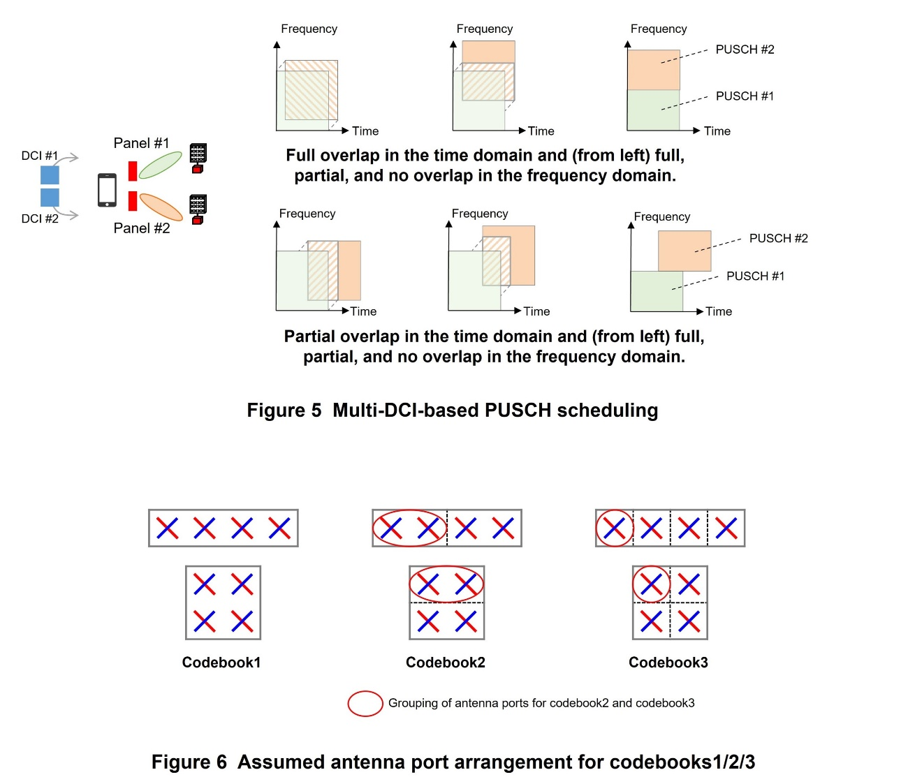
In the case of a non-ideal backhaul environment, the two TRPs cannot coordinate scheduling PUSCH for the UE due to backhaul latency. Thus, as shown on the left side of Figure 5, each TRP independently schedules the PUSCH using their transmitted DCI. Because each TRP schedules PUSCH without coordination, a UE may have simultaneously scheduling of PUSCH by each TRP using a different transmission beam. For such a case, a function is specified for the UE to send two PUSCHs simultaneously using different beams.
Here, because the maximum number of MIMO layers for PUSCH is 4, the number of MIMO layers for PUSCH that each TRP can schedule is limited to 2. Two PUSCH time domain*40 resources that are independently scheduled by two TRPs are supported by full overlap and partial overlap (Fig. 5, right). In addition, two frequency domain resources for PUSCH, independently scheduled by two TRPs, are supported by three schemes: full overlap, partial overlap, and no overlap.
3) Improving UL User Throughput through Maximum 8-layer Data Transmission
Up to Rel-17, specifications were established for PDSCH transmission with a maximum of 8 MIMO layers and PUSCH transmission with a maximum of four MIMO layers. In Rel-18, to further increase UL throughput, the maximum number of layers for PUSCH transmission is extended to 8.
(a) Specification of four types of codebooks
For codebook*41-based 8-layer PUSCH transmission, a total of four types of codebooks (1/2/3/4) are specified. The antenna port layout assumed for codebooks1/2/3 is shown in Figure 6.
Codebook1 assumes all 8 antenna ports are coherent*42 during transmission. Assuming the antenna layout shown on the left side of Fig. 6, it uses Discrete Fourier Transform (DFT)*43 vector as the precoder*44. This follows the Rel-15 Type-I Channel State Information (CSI)*45 codebook for DL. Codebook2 and codebook3 define the 8 antenna ports by separating them into 4x2 and 2x4 (antenna port x group), respectively. They assume coherent antenna ports within the same group but incoherent antenna ports between different groups. For these types, coherent precoders for 4 or 2 antenna ports, respectively, are used. They are specified as UL codebooks in Rel-15.
Unlike the three codebooks described above, codebook4 assumes an implementation where none of the 8 antenna ports are coherent. As the precoder, it simply selects transmission ports, similar to non-coherent precoders for 4-layer PUSCH transmission in Rel-15. Table 1 shows the precoder design for each codebook type.
(b) Enhancement of full power mode 0/1/2
For the purpose of maximizing transmission power when codebooks 2/3/4 are applied, full power mode 0/1/2, which were specified in Rel-16 for PUSCH transmission, have been enhanced to support a maximum of 8 layers for PUSCH transmission. In Rel-16, Mode 0 assumes the implementation of Power Amplifier (PA)*46, which achieves maximum transmission power independently for any antenna port. Mode 1 assumes achieving maximum transmission power by applying coherent precoders to coherent and non-coherent ports. Mode 2 assumes PA implementation that achieves maximum transmission power independently for some antenna ports. In Rel-18, these assumptions are maintained as-is and specifications are extended to enable up to 8 layers for PUSCH transmission.
(c) Other functional extensions for increasing the maximum number of layers for PUSCH
While increasing the maximum number of layers from 4 to 8 for PUSCH, almost the same functions as for PDSCH with more than 5 layers are specified. For example, the number of multiplexed codewords*47 in PUSCH transmission with five or more layers is 2, the same as in PDSCH transmission with five layers or more. The mapping between codewords and layers also applies the rules as-is for PDSCH. In addition, indications of Modulation and Coding Scheme (MCS)*48 /New Data Indicator (NDI)*49 /Redundancy Version (RV)*50 for the second codeword transmitted when two codewords are multiplexed also reuse approaches similar to those specified for DL.
Meanwhile, for Uplink Control Information (UCI)*51 multiplexing, which is a PUSCH-specific function, Rel-18 specifies that when transmitting PUSCH with 5 or more layers, of the two codewords notified, multiplexing of UCI is performed on the codeword with the higher MCS index. The purpose is to maximize the decoding success rate of the multiplexed UCI.
(d) Increasing maximum number of SRS ports
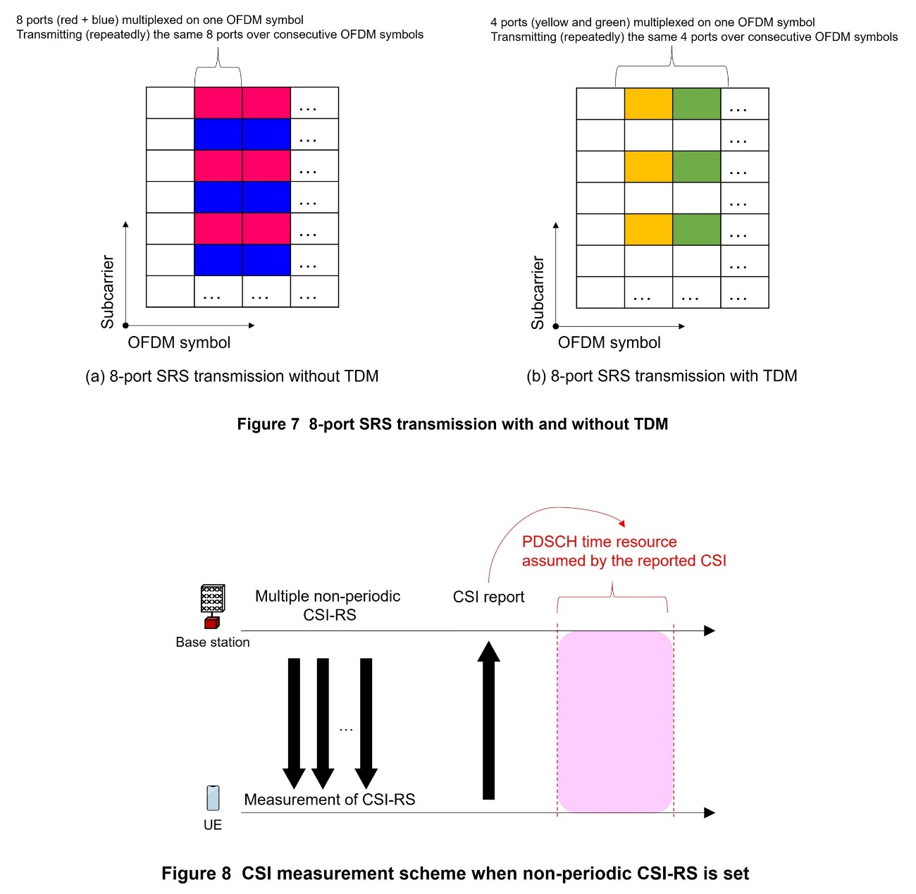
In line with increasing the number of PUSCH layers to 8, the number of Sounding Reference Signal (SRS)*52 ports required for PUSCH transmission is also extended to a maximum of 8. For conventional SRS, all configured SRS ports are transmitted with a single Orthogonal Frequency Division Multiplexing (OFDM) symbol*53. However, an issue is the reduction in transmission power per SRS port when all 8 ports are transmitted with just a single OFDM symbol. To address this issue, in addition to SRS repetitions as specified in previous releases, Rel-18 specifies limiting the number of SRS ports transmitted for one OFDM symbol to 4. Two OFDM symbols are thus consumed when transmitting 8 SRS ports (Time Division Multiplexing (TDM)*54 SRS).
For non-codebook-based PUSCH transmission, the number of SRS resources that can be configured in a single SRS resource set is expanded from 4 to 8, so that the base station can measure the CSI of the UL channel, up to 8 layers, based on the precoder determined autonomously by the UE.
4) Improving UL User Throughput through CSI Extension for UEs Moving at Moderate to High Speed
In Rel-15, two types of CSI codebooks, Type I and Type II, were specified for reporting to the base station by the UE for DL PDSCH transmission. Compared with Type I, Type II has higher quantization granularity*55, and can report spatial beams with the high granularity necessary for MU-MIMO. However, an issue is that compared with Type I codebook, the precoder information reported by TypeⅡcodebook is greatly affected by the Doppler frequency*56 due to reasons such as the UE being in motion. To address this issue, in Rel-18, in addition to the conventional Type II codebook, an enhanced Type II codebook is specified. This codebook allows the UE to measure and report predicted values of the precoder's time variation. This enhancement can improve DL user throughput when the UE is moving at moderate to high speed (e.g., 30-60 km/h).
Concerning CSI measurement, when the UE measures the precoder's time variation and calculates the predicted precoder, it is necessary to measure multiple CSI-Reference Signals (RS)*57 multiplexed in the time domain. It is thus specified that when periodic CSI-RS are set, the UE measures time-varying precoder information from multiple periods of CSI-RS transmission. It is also specified that when aperiodic CSI-RS is used, transmissions of multiple CSI-RS resources are triggered at once and measured by the UE. Figure 8 shows the CSI measurement scheme when non-periodic CSI-RS is set.
Concerning the reported values of precoder time variation information, to minimize the number of bits required for reporting, a DFT vector that can quasi-represent precoder time variation (Doppler frequency variation) expected for each spatial beam and subband*58 is specified. In addition, a CSI report from the UE for this function is multiplexed only on the PUSCH, similar to conventional Type II codebook reporting.

2.2 Reduction of Handover Delay and Increased Flexibility through Handover Enhancements
1) Handover Using Layer 2 (L2)*59 Cell and Beam Indication
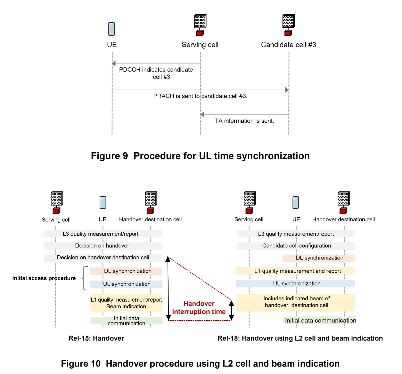
In Rel-15, in Layer 3 (L3)*60, base stations supported the indication of the handover destination cell based on measurements and reports of DL reference signals from the UE. Rel-16 specified simultaneous receiving of signals from both the serving cell*61 and the handover destination cell until the connection is complete. This allows the handover interruption time*62, which occurs during a handover, to be reduced to zero as much as possible. However, issues are the high load on UEs and limited scenarios and frequencies in applying the technology.
Rel-17 enhanced beam management using L1*63/L2 to allow the UE to transmit and receive signals from another cell while remaining connected to the serving cell. This allows signals from another cell to be sent to and received from a UE near the edge of a cell without performing a handover if the received signal power from the other cell is temporarily greater than the received signal power from the serving cell. This method can increase the received power of the transmission and reception signals and user throughput without incurring handover interruption time.
Rel-18 further extends Rel-17 specifications by stipulating the use of L2-based cell and beam indication for handover to the most optimal cell from among handover candidate cells predetermined by the base station based on L1-based beam measurements and reports from the UE.
The base station provides up to eight candidate cell configurations to the UE on L3. By using these configurations, the UE can perform UL/DL synchronization with the candidate cells and L1-based beam measurement/reporting before handover indication.
During UL synchronization, to avoid communication interruption with the serving cell, Rel-18 specifies a method whereby the calculated Timing Advance (TA)*64 is managed at the base station by indicating transmission on a PRACH to the candidate cell on the DL Physical Downlink Control Channel (PDCCH)*65 (Figure 9). Rel-18 also specifies a method to calculate the TA by the UE itself.
For L1-based beam measurement and reporting, to support handover to a cell with different frequency from the serving cell, UE specifications are enhanced so the UE can also measure Synchronization Signals/physical broadcast channel Block (SSB)*66 of candidate cells.
In accordance with the mechanism of L2 cell and beam indication, when the base station indicates the handover destination cell and its beam and the TA acquired by the enhanced method to the UE, the UE stops transmitting and receiving signals vis-à-vis the serving cell and sends and receives signals using the indicated cell and beam. Because candidate cell configurations are maintained even after the handover, they can be used continuously even after the handover.
With this function, because UL/DL synchronization and L1-based beam measurements and reports are carried out before handover indication, Random Access (RA)*67 procedure performed during handover interruption time can be omitted (Figure 10). In addition, when the UE performs a handover within the same Distributed Unit (DU)*68, it is possible to omit resetting Packet Data Convergence Protocol (PDCP)*69 and Radio Link Control (RLC)*70, required for all handover functions from Rel-15 to Rel-17. Handover interruption time can thus be greatly reduced. Also, because handover indication includes beam indication and the beam can be used immediately after handover, handover can be performed while maintaining throughput.
2) Subsequent Conditional PSCell Addition or Change (CPAC)*71
In Rel-17, CPAC was specified for the purpose of improving the reliability and robustness of adding or changing the Primary Secondary Cell (PSCell)*72. However, with Rel-17 CPAC, RRC reconfiguration is necessary each time a PSCell is added or changed. As a result, RRC reconfiguration frequently occurs when the optimal Secondary Cell Group (SCG)*73 is frequently changed, for example when communication is carried out using FR2. To address this issue, Rel-18 extends Rel-17's CPAC function by specifying subsequent CPAC, which allows continuous PSCell addition or change without RRC reconfiguration.
The base station preconfigures the UE with candidate PSCells and conditions for adding or changing the configured PSCells. The conditions are defined based on the UE's measurements of the serving cell and candidate PSCells. Examples of the conditions include the quality of a candidate cell exceeding the quality of the serving cell by a certain threshold or the quality of a candidate cell exceeding a threshold. These conditions need to be updated each time the UE adds or changes a PSCell.
For example, when there are PSCells 1, 2, and 3, and PSCell 1 is the serving cell, the UE evaluates conditions against PSCells 2 and 3. If PSCell 2 fulfills the conditions, the UE connects to that cell. At the same time, conditions are updated, and the UE evaluates the new conditions against PSCells 1 and 3.
By preconfiguring all combinations of conditions for candidate PSCells in the UE and retaining them together with the configurations of candidate PSCells, PSCells can be added or changed continuously without reconfiguring RRC. The result is a significant reduction in signaling*74, which is incurred due to frequent PSCell addition or change.
3) Conditional HandOver (CHO)*75 with Multiple Candidate SCGs
In Rel-16, CHO was specified for the purpose of improving the reliability and robustness of handover. CHO selects the optimal target cell from multiple candidate cells. Conditions for candidate cells are set, and the UE autonomously performs handover to the cell that satisfies the conditions. However, only Primary Cells (PCells)*76 could be set as candidate cells. In addition, when a UE in a Dual Connectivity (DC)*77 state performs CHO, the SCG must be released. Rel-17 enhanced Rel-16's CHO functionality and allowed configuring just one SCG that is associated with candidate PCells. However, the conditions for switching cells could only be set for PCells, not PSCells. It was therefore possible that a non-optimal SCG could be selected when switching cells.
To address this issue, Rel-18 specifies functional enhancements that allow the selection of optimal target cell with both the Master Cell Group (MCG)*78 and SCG. For the UE, in addition to previously specified handover configuration carried out when PCell conditions are met (i.e., CHO configuration) and when PSCell conditions are met (i.e., CPAC configuration), Rel-18 newly specifies configuring handover to be performed only when conditions of both PCell and PSCell are satisfied.
2.3 Low Latency and High Capacity for XR Scenarios
Even before discussions on Rel-18 began, XR had been considered as providing attractive services on mobile network systems in the future. Note that in 3GPP discussion up to Rel-18, XR is an umbrella term for different types of user experience realities: Virtual Reality (VR)*79, Augmented Reality (AR)*80, and Mixed Reality (MR)*81. In Rel-17 and the first half of Rel-18, enhancements specific to addressing issues in XR use cases, i.e., cases when an XR device is connected to a mobile network, were studied. In the second half of Rel-18, technological enhancements were specified from the study with focuses on “XR Awareness*82,” “UE Power Saving,” and “XR Capacity.”
1) XR Awareness
In XR use cases, a high data rate for transmitting video and low latency for reflecting the user's actions in visual information without physical strain are required. Rel-18 therefore specifies functional enhancements for the purpose of transmitting massive amounts of user data with low latency. This is achieved by providing assistance information specific to XR communication from the 5G Core network (5GC)*83 and the UE to the gNodeB (gNB)*84 and by performing more effective scheduling. PDU set information and traffic information are deployed as assistance information reported from the 5GC. For reporting of assistance information from the UE, Rel-18 introduces three technologies. All of them seek to improve UL data transmission.
- One additional buffer size table is newly introduced for the Buffer Status Report (BSR)*85. It improves the granularity of the report of the UL data buffer size. This measure is expected to have the effect of reducing unnecessary resource allocation by the UE.
- A new command (Delay Status Report) is introduced. It allows reporting of the required latency information of delayed UL packets at the same time the UE reports BSR to the gNB. This allows the gNB to allocate resources to preferentially transmit packets that require low latency.
- Rel-18 specifies the ability to report assistance information using UE Assistance Information (UAI)*86 for each Quality of Service (QoS) flow*87 from the UE to the gNB. XR transmission includes multiple types of information of different nature, such as video frames and acceleration information. The specifications assign different types of information for each QoS flow, bringing about XR Awareness for each type of information.
2) UE Power Saving
XR UEs are assumed to be small and lightweight, as exemplified by wearable devices, so their battery capacity is limited. However, XR UEs not only communicate with the gNB but also need to perform operations using limited power, such as processing video information and delivering it to a display. Rel-18 thus specifies two technologies that contribute to reducing battery consumption by the UE for XR use cases.
- A new expression of Discontinuous Reception (DRX)*88 cycle in rational numbers is introduced to match the periodicities of video frames, e.g., 30 fps or 60 fps.
- When the gNB sets the Configured Grant*89 for the UE, the UE can now be instructed not to perform UL repetitions for the transmitted UL signals by using the Configured Grant.
3) Improving XR Capacity
In XR use cases, one cell provides services requiring high throughput, such as video transmission, to multiple UEs. As a result, resource exhaustion by the UEs becomes a bottleneck. Rel-18 thus specifies the following two resource optimization functions with the purpose of allowing more UEs to make concurrent connections.
- For one Configured Grant period, multiple PUSCH transmission opportunities can be set.
- Of the set Configured Grant, Rel-18 specifies that the gNB can reuse resources through reporting sent by the UE to the gNB about resources not actually used in UL transmission.
In addition, the following two functions are specified with the purpose of improving user experience during heavy data traffic. These functions make use of the characteristics of the video data transmitted by XR services.
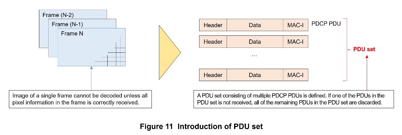
- A group of PDCP Protocol Data Units (PDUs)*90 called a PDU set is newly defined (Figure 11). A PDU set is a set of data where it is assumed that if the transmission or reception of one data packet fails, the decoding*91 of other packets also fails, e.g., data that make up a frame of video. Based on this assumption, Rel-18 specifies a function that discards an entire PDU set if there are packets missing in the set.
- Rel-18 specifies that the gNB can set the level of transmission priority on a per-PDU set basis. During network congestion, the UE can be instructed to discard low-priority PDU sets ahead of high-priority PDU sets.
2.4 Enhancements of Multi-carrier Operation
As 5G networks expand since Rel-15, 3rd Generation mobile communications system (3G) and 4th Generation mobile communications system (4G) are being retired. Accordingly, it is considered that there will be more opportunities to assign FR1 bands previously used by 3G/4G to 5G. Because the frequencies that will be used for 5G in this manner are often fragmented and narrowband, multi-carrier operation across multiple bands is required. FR2 bands (and some FR1 bands), on the other hand, can secure sufficient bandwidth, so it is considered that there will be many opportunities to achieve high-capacity communication through multi-carrier operation within the same band. Rel-18 specifies two features for the purpose of improving throughput in inter-band and intra-band multi-carrier operation: reduction of control signal overhead and increasing the flexibility of UL dynamic scheduling.
1) PDSCH/PUSCH Scheduling for Multiple Cells Using Single DCI
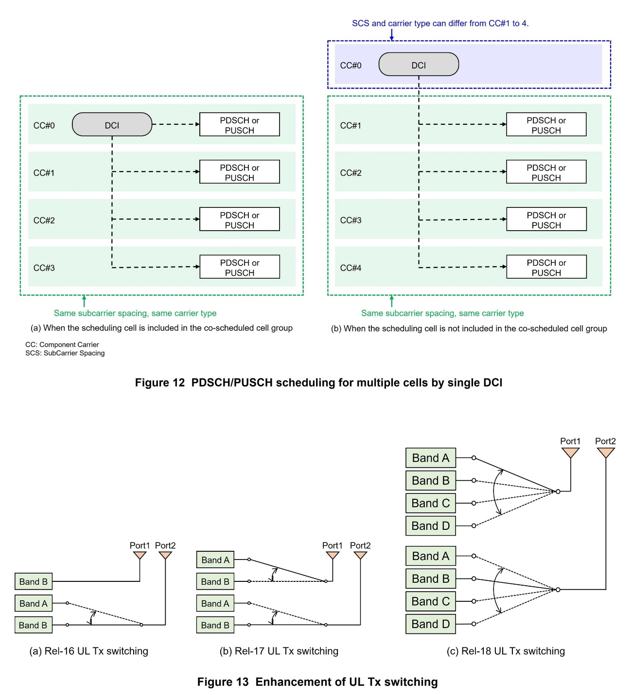
As shown in Figure 12, Rel-18 introduces a function that allows the DCI in a single cell to schedule for multiple cells. The newly specified DCI format 0_3 and DCI format 1_3 can simultaneously schedule the PUSCH and PDSCH of up to four cells. DCI format 0_3 is used to schedule the PUSCH of multiple cells. DCI format 1_3 is used to schedule the PDSCH of multiple cells. The target cells can be either intra-band or inter-band. However, they must have the same subcarrier spacing*92 and be of the same carrier type (licensed or unlicensed, FR1 or FR2-1 or FR2-2). Note that the scheduling cell can either be included (Fig. 12 (a)) or not included (Fig. 12 (b)) in the group of co-scheduled cells. By aggregating the control information of multiple cells in a single DCI, reduction of overhead for control and increase in spectral efficiency*93 can be expected.
2) Further Enhancement of UL Tx Switching
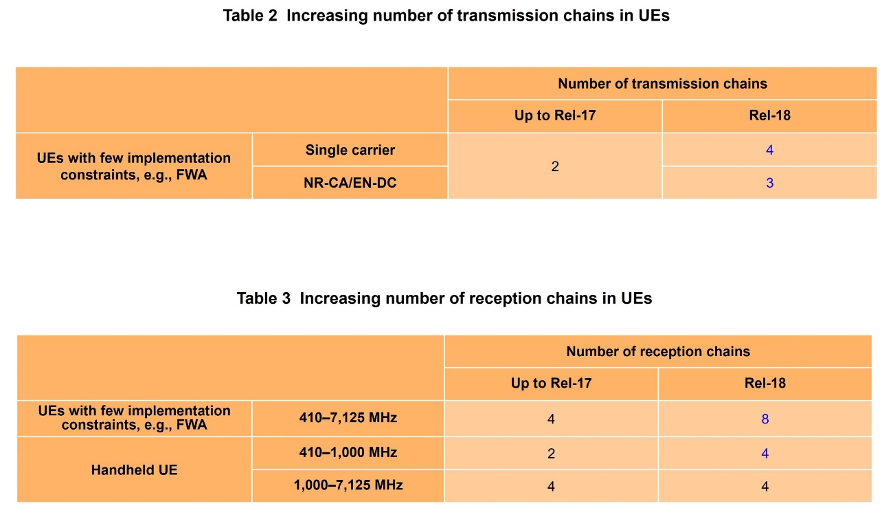
As shown in Figure 13 (a), in Rel-16 a function called UL Tx switching is specified. For UL transmission with two ports, two bands make up one of the ports, and the function dynamically switches between the two transmission bands. As shown in Fig. 13 (b), in Rel-17, two bands make up each port, and switching in both ports can be performed. As shown in Fig. 13 (c), Rel-18 further expands dynamic switching in the ports, to four bands per port, resulting in more switching patterns.
Note that immediately before and after dynamic switching, a duration of time during which transmission is not performed, called the switching period, is set. In Rel-16 and Rel-17, because switching is between two bands, a single switching period is set. On the other hand, in Rel-18, switching is between three or four bands, so a switching period is set for each band pair. Specifications are established to clarify the duration and insertion point of the switching period applied to each switching period. With the introduction of Rel-18 UL Tx switching, more flexible UL transmission scheduling is possible, leading to increased throughput and capacity.
2.5 FR1 UE RF Functional Enhancements to Improve User Throughput
1) Increasing Number of Transmission Chains in UEs to Improve UL User Throughput
To further increase UL throughput, the number of transmission chains in the UE radio analog circuit is expanded for Fixed Wireless Access (FWA)*94, Customer Premises Equipment (CPE)*95, and vehicular and industrial UEs, which, compared with Handheld UEs*96, have fewer constraints in implementation. Table 2 shows the number of expanded transmission chains for single carrier transmission and NR Carrier Aggregation (CA)*97 /Evolved Universal Terrestrial Radio Access Network New Radio Dual Connectivity (EN-DC)*98 -based transmission.
(1) Expansion to 4 simultaneous transmission chains in single-carrier transmission
Rel-18 expands the maximum number of simultaneous chains for single-carrier transmission from 2 chains to 4 chains. In addition to effectively increasing UL throughput through Tx diversity*99, further increase in UL peak rate is expected by using 4-layer MIMO for UL transmission. This function applies to both Frequency Division Duplex (FDD)*100 and Time Division Duplex (TDD)*101 bands.
The maximum transmission power when four chains are transmitted is 29 dBm. The power amplifier configurations in the UE are expected to consist of three patterns: four power amplifiers with transmission output of 23 dBm, two power amplifiers with respective transmission output of 23 dBm and 26 dBm, respectively, or four power amplifiers with transmission output of 26 dBm. With regard to specifications concerning various interferences emitted from the UE, the aggregate value of the signal levels measured from four antenna connecters is specified at the same level as previous two-chain transmission or one-chain transmission to maintain the total amount of interference. Therefore, there are no changes to conditions for sharing adjacent frequencies with other systems.
(2) Expansion to simultaneous transmission by 3 chains in NR CA/EN-DC
UL inter-band NR CA/EN-DC*102 is enhanced to simultaneously transmit 3 chains from the previous maximum 2 chains. When using 2 bands for simultaneous transmission, previously up to 1 Tx (one-chain transmission) could be used on each band; i.e., a total of 2 Tx (1 Tx + 1 Tx) could be used. In contrast, Rel-18 allows simultaneous transmission of a total of 3 Tx; this is made possible by enabling up to 2 Tx on one band, resulting in 1 Tx + 2 Tx. This enhancement is expected to improve UL throughput. At present, FWA is targeted as the applicable UE, and up to 29 dBm is specified as the total transmission power when transmitting 3 Tx. As part of the deployment of 3 Tx, transmission performance specifications are provided respectively for UL 2-layer MIMO and Tx diversity on the 2 Tx side. In addition, for reception performance, new specifications are introduced that take into account the interference due to intermodulation*103 when the total transmission power is 29 dBm.
2) Increasing Number of Reception Chains in UE to Improve DL User Throughput
To further increase DL throughput, Rel-18 increases the number of reception chains in the UE radio analog circuit. Table 3 shows the number of expanded reception chains by UE type and frequency band.
(1) Increase to 8 simultaneous reception chains for UEs such as FWA with few implementation constraints
This enhancement targets FWA, CPE, vehicular UEs, and industrial UEs, which have fewer implementation constraints compared with handheld UEs. The number of maximum DL reception chains is expanded from 4 to 8. This enhancement is expected to not only increase effective Rx diversity-based DL throughput but also increase DL peak rate through DL 8-layer MIMO reception. This function is applicable to both FDD and TDD bands, and is assumed to also apply to single carrier and NR CA/EN-DC. For reference sensitivity*104, the specifications enable achieving the same throughput with reception power 1.6 dB to 1.8 dB (the value varies depending on the frequency band) lower compared to when 4 chains are installed, increasing DL coverage. In relation to SRS antenna switching*105, introduced in a previous release, reduction in the UE's transmission power during SRS antenna switching was also discussed. This is because by increasing the number of connection candidates when connecting transmission chains to each antenna in the UE to 7, the number of layers in the internal RF switch structure increases, and loss that occurs as part of switch insertion increases.
(2) Increase to 4 simultaneous reception chains for handheld UEs in low-frequency bands below 1 GHz.
In general, the lower the frequency, the larger the size of the antenna. For small UEs like handheld UEs, special attention needs to be given to the size and number of installed antennas. In Rel-15, specifications related to 4-chain reception were introduced. In subsequent releases, target bands were also added. However, up to Rel-17, specifications for bands below 1 GHz were limited to FWA, which is large in size for a UE.
To address this issue, in Rel-18, specifications concerning 4-chain reception of bands under 1 GHz are expanded so that implementation in handheld UEs is possible. Low-frequency bands under 1 GHz are suitable for wide-area coverage. In Japan, the 700-900 MHz band is an extremely valuable frequency band. On the other hand, compared with higher frequency bands such as the 3.7 GHz, 4.5 GHz, and 28 GHz bands allocated for 5G, the low-frequency bands face throughput issues due to their narrow bandwidth. Enhanced specifications in Rel-18 are expected to improve DL throughput in handheld UEs by increasing the number of simultaneous reception chains from 2 to 4, even for low-frequency bands.
3) Increasing System Capacity by Reporting Degradation in Reception Sensitivity due to Self-transmitted Signal Coupling*106 in UE
When simultaneous transmission and reception in NR CA/EN-DC are carried out, signal degradation occurs due to coupling of self-transmitted signals in the UE. Rel-18 specifies a method to reduce this degradation by combining measures with UE capability information*107. This function makes it possible for the network side to distinguish between UEs with implementation of good performance and those that do not. More suitable scheduling is expected as a result.
The specified function allows the amount of UE sensitivity degradation to be reported by the UE capability for each combination of frequency bands that make up NR CA/EN-DC and causes of intra-UE interference such as harmonics*108 and intermodulation. The specifications also introduce a signaling framework to reduce the signal size. The same amount of sensitivity degradation can be notified uniformly for multiple causes of interference within the UE.
4) Improving System Capacity by Introducing CA/DC Specifications in Environment with Non-adjacent Base Station Antennas
In previous releases, the frequency specifications of LTE Band 42 (3.4 to 3.6 GHz) and NR Bands n77 (3.3 to 4.2 GHz) and n78 (3.3 to 3.8 GHz) were treated as intra-band NR CA/EN-DC*109. The reference performance specifications of UEs assumed the physical placement of adjacent base station antennas. As a result, the differences in received signal power between these bands in NR CA/EN-DC and in their signal reception and transmission times did not take into consideration differences in propagation paths. However, in reality, in some cases base station antennas for these bands are installed in physically separate locations because the base stations for each frequency were built at different times or the areas where they could be built were limited. In such cases, the UE cannot satisfy the reference performance specifications because NR CA/EN-DC operation that combines these bands is difficult to carry out.
To address this issue, UE composition of two separate transmission and reception components for each band has been studied. This is to ensure that the acceptable range of the differences between the received and transmitted power signals and their times can be the same as the inter-band NR CA/EN-DC (Figure 14). In Rel-16 and Rel-17, specifications expanded each band in EN-DC to two layers for a total of four layers. In Rel-18, these specifications are expanded to include NR-CA. As a result, the allowed difference in received signal power, previously limited to 6 dB, is now increased to 25 dB. The allowed difference in their times is increased to 30 μs longer compared with the previous difference. This enhancement is expected to allow flexible base station placements and band combinations.

2.6 FR2 UE RF Functional Enhancements to Improve User Throughput
1) Enhancement of Modulation Methods to Increase UL User Throughput
For the modulation method in FR2, 256-Quadrature Amplitude Modulation (QAM)*110 can be used for DL from Rel-16 and 64-QAM can be used for UL from Rel-15. To further increase UL throughput, Rel-18 deploys 256-QAM for UL to increase communication capacity that results from its use. Compared with 64-QAM, which transmits 6 bits per symbol, 256-QAM transmits 8 bits per symbol, so it can transmit 8/6 times the information of 64-QAM at once. This increased capacity is expected to play a major role in use cases involving over-Gbps capacity in low path loss*111 environments. However, at present, this function targets bands defined in the 24.25-43.5 GHz range and is assumed to be used for FWA and vehicular UEs, where there are fewer constraints in implementation compared with handheld UEs. This is because it is necessary to guarantee the base station's received Signal to Noise Ratio (SNR)*112 and take into consideration issues such as power consumed by the UE and the heat it generates.
In addition, in introducing 256-QAM for UL for FR2, Rel-18 specifies Error Vector Magnitude (EVM)*113 that should be ensured in the UE and the allowed transmission power backoff *114.
2) Enhancement of Transmission Beam Management in UE to Improve Connectivity
Proper beam management is extremely important for FR2. This is because propagation characteristics in FR2, such as high directivity and atmospheric absorption, make it difficult to transmit radio waves over a long distance. Rel-15 thus introduced beam correspondence for FR2. This function manages the beam on the UE side by determining the UL transmission beam based on DL measurements using the reception beam. After Rel-15, there have been discussions on enhancing beam correspondence. However, only performance requirements for the RRC_CONNECTED*115 state has been specified up to Rel-17. In Rel-18, performance requirements are specified for the initial access in the RRC_IDLE*116 and RRC_INACTIVE*117 states.
Spherical coverage*118 for UEs in the RRC_CONNECTED state has already been specified to ensure that the beam has the intended direction and range. Rel-18 added specifications for the performance of initial access and the RRC_INACTIVE state and makes spherical coverage 2 dB lower than that of the RRC_CONNECTED state. Because these specifications ensure high-quality UL transmission beam, improved UL coverage performance and connectivity are expected. Power saving and latency reduction effects are also expected due to the RRC_INACTIVE state and Small Date Transmission (SDT)*119 introduced in Rel-17.
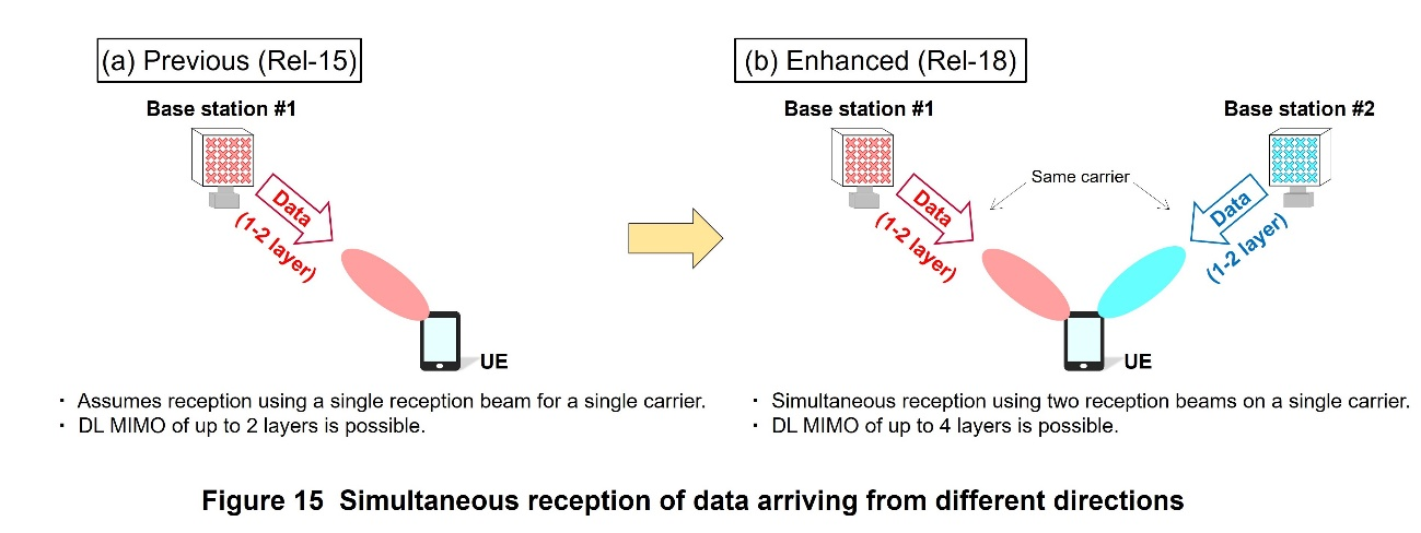
3) Simultaneous Reception of Data from Different Directions to Improve DL User Throughput
Rel-15 assumes that for FR2, a single reception beam selected from formed directivity*120 patterns is used; in other words, multiple reception beams are not used. The reception performance of the UE is specified based on this assumption (Figure 15 (a)). The specifications of DL MIMO for FR2 allow a maximum of 2 layers per beam, so 4-layer reception, which is generally used in FR1, cannot be achieved with a single reception beam. Rel-16 and Rel-17 thus specified reception requirements for FR2 NR CA. The specifications assume a UE with two signal processing units. In scenarios where data arrives simultaneously from different carriers that make up the CA, DL simultaneous reception is achieved by forming independent reception beams for each carrier. Each carrier has up to two layers. It is possible to thus achieve simultaneous reception that is equivalent to four layers by bundling multiple carriers.
As shown in Fig. 15 (b), Rel-18 specifies performance based on the assumption of scenarios where DL data on single carriers from different directions are simultaneously received using 2 reception beams. Because this makes it possible to simultaneously receive using 4 layers on a single carrier, improvements in DL throughput and spectral efficiency are expected. The specifications enhance the UE's spherical coverage to include scenarios where data arrives simultaneously from multiple directions. At present, these enhancements target bands defined within 24.25-43.5 GHz in FR2. The Angle of Arrival (AoA) separation*121 conditions suitable for UE implementation should be applied.
In addition, as part of this RF functional enhancement, Radio Resource Management (RRM)*122 is also enhanced by utilizing multiple beams. For FR2, it is assumed that the UE forms the reception beam not only when transmitting and receiving signals but also for measuring radio quality. Because a particular beam can measure radio quality only in a particular direction, beam sweeping*123 by the UE is required to broadly measure the surrounding environment. This operation results in the same radio quality measurement taking longer for FR2 than FR1. Furthermore, in cases where the reference signal for quality measurement and PDSCH are frequency-multiplexed, PDSCH reception is limited because the UE is performing beam sweeping; i.e., there is also the limitation that DL data cannot be received. In response to these issues, the time required to measure radio quality can be reduced by equipping the UE with multiple reception elements and having each element perform beam sweeping independently and simultaneously. In addition, to deal with the limitation of the inability to receive data during radio quality measurement, data can be simultaneously received by using CSI-RS as the reference signal for quality measurement. Improvement in DL throughput is expected as a result.
- MU-MIMO: Technology for performing MIMO communications using the receive antennas of multiple users. Dividing spatial streams among users enables user multiplexing.
- PDSCH: A DL physical channel for transmitting user data and control information from the higher layer signaling.
- PUSCH: Physical channel used for sending and receiving data in the UL.
- SDM: Multiplexing method in which orthogonal codes are transmitted using separate spatial beams.
- MIMO layer: A specific MIMO spatial stream.
- DMRS: Base station signal transmitted to measure radio channel conditions for demodulation.
- DMRS port: Orthogonal DMRS resources allocated to each MIMO layer.
- SU-MIMO: MIMO communications using multiple transmitting and receiving antennas for a single user.
- DMRS Type1: A DMRS configuration specified in Rel-15.
- Overhead: Radio resources used for non-user data transmission, such as control information needed for transmitting and receiving user data and reference signals for receiving data.
- FD-OCC: Application of orthogonal codes to resources in the frequency domain.
- Physical layer: Layer 1 in the Open Systems Interconnection (OSI) reference model. This layer performs modulation of radio frequency carriers and coded data modulation for radio signal transmissions.
- CDM group: Frequency resources to which the same FD-OCC applies.
- PRE: One subcarrier of a single OFDM symbol.
- PRB: The smallest unit of resource allocation, consisting of 12 consecutive orthogonal subcarriers.
- Walsh code: Orthogonal code generated from a square matrix of order 2n (where n is a natural number) consisting of elements +1 or -1.
- Cyclic shift: Generation of maximum of N orthogonal codes by applying a different phase rotation (S0x0xα, S1x1xα, …, SN-1x(N-1)xα) at regular intervals for each sequence index (n = 0, 1 , …, N-1) of a sequence (S0, S1, …, SN-1).
- Advanced UE capability: Advanced UE functions in contrast to basic UE functions.
- TRP: A set of one or more transmitter/receiver antenna ports installed at a single location in a base station. A base station configuration that uses only one transmitter/receiver antenna port at a single location is called a single TRP, while a base station configuration that uses multiple transmitter/receiver antenna ports at multiple locations is called multi-TRP.
- DL: Flow of information from the base station to the UE.
- PUCCH: Physical channel used for sending and receiving control signals in the UL.
- Backhaul: Links from the core network to wireless base stations. In this article, it refers to the links between TRPs.
- DCI: Control information transmitted on the DL that includes scheduling information needed by each user to demodulate data and information on data modulation and channel coding rate.
- SFN: Method of transmitting the same signal from multiple transmitting antennas using different transmission beams in the same frequency-time resource.
- Time domain: In signal analysis, this domain is used to show the temporal makeup of a signal's components. A time-domain signal can be converted to a frequency-domain signal by Fourier transform.
- Codebook: A set of predetermined precoding weight matrix candidates.
- Coherent: Here, it means that the phase of the signal is calibrated within a certain range between ports, and it is possible to multiply the precoder (see *44) across those ports.
- DFT: Discrete Fourier transform.
- Precoder: Coefficient by which given digital signals are multiplied before transmission to cancel multiuser interference.
- CSI: State of the radio channel between the base station and the UE.
- PA: Determines the intensity of power applied to the transmitted signal.
- Codeword: A unit of transmitted information.
- MCS: Modulation method and coding rate. Or the bits in the Downlink Control Signal (DCS) for their notification.
- NDI: Notification bit in the DCS that indicates whether the data signal to which resources have been allocated is the first transmission of a certain codeword or its retransmission.
- RV: Notification bit in the DCS that indicates the part of the modulated and encoded signal that is actually transmitted by the sender.
- UCI: A general term for UL signals such as HARQ-ACK, CSI, and SR.
- SRS: UL reference signal used at the base station to measure UL channel quality, reception timing, etc.
- OFDM symbol: A unit of transmission data, consisting of multiple subcarriers in the case of OFDM. A Cyclic Prefix (CP) is inserted at the front of each symbol.
- TDM: Time division multiplexing.
- Quantization granularity: The spatial granularity of beams that are capable of being formed.
- Doppler frequency: Error in frequency caused by the movement of the transmitter or receiver in wireless communications.
- CSI-RS: A DL reference signal used by the UE to measure the state of the radio channel.
- Subband: Here, the assumed granularity of reporting in the frequency domain for CSI report.
- L2: The second layer (the data link layer) in the OSI reference model.
- L3: The third layer (the network layer) in the OSI reference model.
- Serving cell: The cell where the UE currently has established a radio link.
- Handover interruption time: The period during a handover when the UE cannot send or receive user data to or from the base station.
- L1: The first layer (physical layer) in the OSI reference model.
- TA: The amount of timing adjustment on the UE side to maintain signal orthogonality between multiple UEs.
- PDCCH: Control channel for the physical layer in the DL.
- SSB: Synchronization signal for detecting cell frequencies and timing required for communication and broadcast channel notifying of main radio parameters. Sent periodically by the base station.
- RA: A procedure performed when the UE establishes a connection with the base station or resynchronizes with the base station at the time of an outgoing call or handover.
- DU: Distributed nodes in an architecture that uses LTE and NR radio links simultaneously.
- PDCP: A sublayer in Layer 2, and is a protocol that performs functions associated with confidentiality, authenticity, sequencing, header compression, etc.
- RLC: A sublayer for radio interface in Layer 2, and is a protocol that performs functions such as controlling retransmission.
- CPAC: Procedure for adding or modifying PSCells as specified in Rel-17. When the execution conditions configured in UE are met, the target PSCell is added or modified.
- PSCell: Of the cells included in the SCG (see *73) in DC (see *77), the cell that maintains the connection.
- SCG: A cell group under the Secondary Node (SN) base station from among the base stations in DC.
- Signaling: Control signals used for communication between terminals and base stations.
- CHO: Operation in which the UE sets candidate cells for handover and handover execution conditions. When the execution conditions are met, the UE performs the handover autonomously.
- PCell: The carrier essential to keep the connection with multiple carriers in CA. Also referred to as the primary cell.
- DC: Technique that achieves high-throughput transmission by connecting to two base stations (master and secondary) and simultaneously transmitting and receiving signals using multiple carriers supported by those base stations.
- MCG: A cell group under a base station (Master Node (MN) that establishes a connection with the UE in DC.
- VR: Technologies that provide the sensation of being immersed in a virtual world by blocking out visual and audio information from the real world while simultaneously providing visual and audio information from the virtual world via the device.
- AR: Technologies that integrate the real world and virtual world by overlaying additional information such as visual objects on top of the real environment.
- MR: Further development of AR whereby technologies create the sensation that virtual objects are part of the real world by changing their forms to match the real world and allowing their manipulation and interaction.
- XR Awareness: Technologies that improve scheduling operations for XR communication by allowing the gNB (*see 84) to take into account conditions specific to XR communication.
- 5GC: 5G-dedicated core network.
- gNB: 5G NR base station.
- BSR: A type of Medium Access Control Control Element (signal) (MAC CE) transmitted in the UL MAC sublayer. It is used by the UE to report the amount of UL data buffered in the gNB that it wishes to transmit. MAC is one of the sublayers in radio interface Layer 2. It refers to the protocols that perform radio resource allocation, data mapping to the Transport Block (TB), Hybrid Automatic Repeat Request (HARQ) retransmission control, etc.
- UAI: A type of RRC message. It is used by the UE to report its internal information to the gNB.
- QoS flow: A flow that represents a unit for performing QoS control. Note that QoS control is a technique that controls the quality of communication, such as by giving priority to the transmission of packets.
- DRX: Intermittent reception control used to reduce power consumption in UE.
- Configured Grant: A mechanism for allocating PUSCH resources beforehand from the base station on a user-by-user basis so that UE can transmit PUSCH by those resources if UL data is generated without having to transmit a Scheduling Request (SR).
- PDU: A unit of data processed by a protocol layer/sub-layer.
- Decode: Reconverting data compressed with encoding equipment back to video data.
- Subcarrier spacing: The interval between individual carrier waves transmitting a signal in multi-carrier transmission such as OFDM.
- Spectral efficiency: The number of data bits that can be transmitted per unit time and unit frequency band.
- FWA: Type of radio communication standard. Unlike mobile UEs such as smartphones, fixed wireless access is designed to be used in a fixed location, so its communication standards are generally easier to implement in UEs larger than mobile devices.
- CPE: Type of radio communication standard for radio system installed at a customer's premises. In general, the standards are easier to implement in UEs larger than mobile devices.
- Handheld UE: UE such as a smartphone that is held in the user's hand.
- NR CA: Refers to a communication scheme in which the NR frequency bands are bundled to achieve wideband.
- EN-DC: A technology that achieves wideband communication by bundling the LTE frequency band with the NR frequency band.
- Diversity: To improve communication quality, signals are received or transmitted using multiple antennas. Signals with best reception (transmission) conditions are selected and combined.
- FDD: Method of signal transmission that uses different frequencies for UL and DL.
- TDD: Method of signal transmission that uses the same frequency for UL and DL and divides the transmission into time slots.
- Inter-band NR CA/EN-DC: NR CA/EN-DC composed of different frequency bands.
- Intermodulation: When signals of multiple different frequencies are input into a nonlinear circuit, such as an amplifier, the combination of input frequencies can result in the output of signals with undesired frequency components.
- Reference sensitivity: UE reception performance standard that defines the Rx power level required to achieve the reference throughput.
- SRS antenna switching: Function that estimates the DL propagation path by connecting the transmission streams inside the UE to multiple receiving antennas and then transmitting SRS.
- Coupling: A phenomenon that occurs when signals transmitted from a transmit antenna on radio equipment are received by a receive antenna on the same equipment.
- UE capability information: Signaling that notifies the base station of the status of the UE's capabilities.
- Harmonic: A higher-order frequency component that is a positive integer multiple of a wave with a certain frequency component.
- Intra-band NR CA/EN-DC: NR CA/EN-DC composed of the same frequency band.
- QAM: A type of modulation method that uses both amplitude and phase for modulation. There are different schemes, such as 16-QAM, 64-QAM, 256-QAM, and 1024-QAM, depending on the number of defined states.
- Path loss: Propagation path loss estimated from the difference between the transmitted power and received power.
- SNR: The ratio of the desired signal power to the noise power.
- EVM: An index of communication quality indicating the magnitude of error with respect to the original signal point.
- Transmission power backoff: Reduction of transmission power. In this article, this refers to a relaxation of the specifications on the maximum output power that must be maintained by the UE.
- RRC_CONNECTED: One of the RRC states of the UE, where resources have been allocated between the UE and base station.
- RRC_IDLE: A UE RRC state in which the UE has no cell-level identity within the base station and the base station stores no UE context. The core network stores UE context.
- RRC_INACTIVE: A UE RRC state in which the UE does not have cell-level identity within the base station. The context of the UE is held in both the base station and the core network.
- Spherical coverage specification: Specification of range of solid angles that a UE can cover. Uses the cumulative distribution of each Equivalent Isotropic Radiated Power (EIRP), which is the transmission power at a specified point in the radio wave radiation space, or each Equivalent Isotropic Sensitivity (EIS), which is the receiving power at a specified point in the radio wave radiation space obtained, when the beam direction is manipulated over the entire spherical surface centered on the UE. EIRP values are measured for transmission specifications, and EIS values are measured for reception specifications to achieve the reference DL throughput. This specification statistically ensures that the beam is properly directed in the intended direction (in the direction of the communicating base station) and within the required range. Using the measured values, spherical coverage is defined as X% of spherical space where EIRP or EIS values are guaranteed.
- SDT: A new function for IoT UEs introduced in Rel-17 that allows the UE to send small amounts of packet data by using random access or CG resources while in RRC_INACTIVE state.
- Directivity: An antenna radiation characteristic indicating the directional characteristics of radiation strength (or reception sensitivity) from the antenna.
- AoA separation: Difference in arrival angle of two signals arriving at the same time.
- RRM: A generic term for resource management including mobility operations such as handover or measurement of cell quality via reference signals in order to manage limited radio resources or connect between terminals and base stations smoothly, etc.
- Beam sweeping: When using multiple beams, the spatial sweeping of those beams by switching from one to another continuously.
-
3.1 PRACH Repetitions
Open
Rel-17 specified enhancement of transmission repetitions for the purpose of enhancing PUSCH and PUCCH coverage. However, it has been observed that in the cell where PUSCH and PUCCH coverage are expanded, PRACH coverage could become the bottleneck of the overall cell coverage. To address this issue, PRACH repetitions are specified in Rel-18.
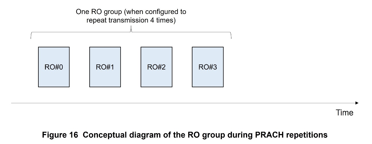
Resources for PRACH transmission are configured based on the RACH Occasion (RO)*124 and PRACH transmission sequence*125 within the RO. This method of configuration is also used almost as-is for PRACH repetitions. Meanwhile, to achieve coverage enhancement through repetitions, the base station needs to be aware that a set of PRACH transmissions are repetitions from a UE. To achieve this, of the ROs associated with an SSB index, the same number of ROs that are multiplexed in the time domain as the number of set repetitions (2, 4, or 8 can be set) are defined as an RO group. When a UE performs PRACH repetitions, the use of the same PRACH preamble*126 within an RO group is specified. A conceptual diagram of an RO group is given in Figure 16.
Prior to Rel-18, the UE determines the start of PRACH transmission by comparing the SSB measurement result (Reference Signal Received Power (RSRP)*127) from the UE and a set threshold value. PRACH repetitions are advantageous for coverage but also have the drawback of reducing the efficiency of radio resource utilization. How to appropriately define and configure cases where the UE performs PRACH repetitions was thus discussed. This led to the definition of a threshold value for the SSB reception result (RSRP), separate from the RSRP for determining the start of PRACH transmission, for the purpose of determining whether or not the UE should begin PRACH repetitions and the number of repetitions. The number of PRACH repetitions is specified by comparing the difference in size between this new threshold value and the SSB reception result (RSRP). For example, if the threshold value for determining the start of PRACH transmission is set as -40 dBm and the threshold value for performing two PRACH repetitions is set as -43 dBm, the UE performs two PRACH repetitions if the SSB measurement result (RSRP) is -43 dBm or greater and less than -40 dBm. If the SSB measurement result (RSRP) is -40 dBm or greater, the UE performs PRACH transmission (without repetitions). In this way, each UE can determine the number of needed PRACH repetitions.
3.2 Improving UL Transmission Power Efficiency
1) Enhancement of ΔP_PowerClass
In Rel-15 NR, a framework called ΔP_PowerClass is available for reducing the maximum transmission power of High Power UEs (HPUEs)*128. Maximum transmission power is reduced when the UL ratio is exceeded during an evaluation time period (UL/DL/Gap period). This ratio is specified in UE capability information as part of guidelines to protect the human body.
However, an issue was that it was unclear on the network side if the cause of decrease in UE transmission power was due to the application of ΔP_PowerClass or some other factors. Rel-18 thus allows the UE to notify the network of reduction of transmission power due to exceeding the UL ratio supported by the UE and of operation to return to the original upper limit of transmission power. This enhancement allows the network to take into consideration the output power achievable by the UE when optimizing resource scheduling.
2) Introduction of Power Boosting
For the purpose of expanding UL coverage, power boosting is introduced for π/2 Binary Phase Shift Keying (BPSK)*129 and Quadrature Phase Shift Keying (QPSK)*130 modulation schemes. The functions increase the maximum transmission power output of UEs under Power Class (PC)3*131 and PC2 from their previous limits by up to 1 dB. Two power boosting methods are introduced for use depending on the applicable RB range and whether or not there is spectral flatness*132 requirement relaxation.
- The first power boosting method applies only to a part of RB allocation in inner RB allocation*133 and does not require relaxation of existing spectrum flatness.
- The second method allows power boosting for all RB allocation that corresponds to inner RB allocation. It requires relaxation of some existing spectrum flatness values.
Networks can be notified of the state of a UE's support of the two methods by each UE capability.
3.3 Dynamic Switching of UL Waveforms
Rel-15 specified two types of waveforms, Cyclic Prefix-OFDM (CP-OFDM)*134 and DFT-Spreading-OFDM (DFT-S-OFDM)*135, for UL PUSCH transmission. CP-OFDM is superior in terms of flexibility in resource allocation in the frequency domain, while DFT-S-OFDM is superior in terms of coverage because of the low Peak to Average Power Ratio (PAPR)*136 of its generated signals. In Rel-15, these waveforms can be switched only by RRC configuration. For example, when a cell is operated such that DFT-S-OFDM is applied to users at the edge of the cell and CP-OFDM is applied to users near the center of the cell, once the UE moves between the cell's edge and center, the issue of RRC reconfiguration always being necessary occurs. To address this issue, Rel-18 specifies the switching of waveforms by the DCI without the need for RRC reconfiguration. Specifically, a one-bit indication field (Transform Precoder Indicator: TPI) is added to DCI format 0_1 and 0_2, which determines the waveform to be applied to the schedule UL PUSCH. If the TPI is 0, DFT-S-OFDM is applied to the scheduled PUSCH. If the TPI is 1, CP-OFDM is applied.
Meanwhile, the difference between DFT-S-OFDM and CP-OFDM in terms of coverage changes depending on the resource allocation to PUSCH and the MCS to be applied. To allow a base station to understand the difference in coverage between the two waveforms, Rel-18 thus specifies the function to report in the already specified Power Headroom Report (PHR)*137 the maximum transmission power calculated based on the application of CP-OFDM and DFT-S-OFDM.
- RO: Physical resources configured for transmitting PRACH.
- PRACH transmission stream: The sequence of transmitted bits defined as PRACH. A Zadoff-Chu sequence is used for NR.
- Preamble: A signal with a fixed pattern positioned at the beginning of packets. Receivers use these to detect packets, control gain, and synchronize frames and frequencies etc. as preparation to receive the data portion.
- RSRP: Received power of a signal measured at the UE. RSRP is used as an indicator of receiver sensitivity in the UE.
- HPUE: UE that can transmit with maximum transmission power greater than the standard 23 dBm.
- π/2 BPSK: A digital modulation method where binary information is transmitted via two phase states.
- QPSK: A digital modulation method where 2-bit information is transmitted via four phase states.
- PC3: UE functioning with maximum antenna power of 23 dBm, as specified by the Power Class, which defines the maximum antenna power that can be transmitted by a UE.
- Spectral flatness: UE transmission specifications to ensure that the power levels of the transmission bandwidth are equivalent between different frequencies.
- Inner RB allocation: RB arrangement with consecutive middle bandwidth.
- CP-OFDM: A waveform generation method that adds the processing called CP—inserting a copy of the trailing part of the signal to the head of the signal—for time-domain signals generated by an Inverse Fast Fourier Transform (IFFT).
- DFT-S-OFDM: A waveform generation method that applies DFT to a signal when generating frequency-domain signals before CP-OFDM processing.
- PAPR: The ratio of a signal's maximum power to its time-averaged power when the signal is generated at any given time.
- PHR: Signal that reports to the network the actual transmission power relative to the maximum transmission power.
-
This article has described major functionalities ...
Open
This article has described major functionalities of the Rel-18 NR specifications to achieve higher throughput and higher capacity. The use of Rel-18 NR functionalities, including those described in this article, is expected to further enhance the user experience of 5G NR communication networks. NTT DOCOMO will continue promoting standardization activities at 3GPP to contribute to the technological advancement and proliferation of 5G.
-
REFERENCES
Open
- [1] K. Takeda et al.: “NR Physical Layer Specifications in 5G,” NTT DOCOMO Technical Journal, Vol. 20, No. 3, pp. 49-61, Jan. 2019.
 https://www.docomo.ne.jp/english/binary/pdf/corporate/technology/rd/technical_journal/bn//vol20_3/vol20_3_007en.pdf (PDF format:1,292KB)
 - [2] Y. Matsumura et al.: “5G Advanced Technologies for Mobile Broadband,” NTT DOCOMO Technical Journal, Vol. 22, No. 3, pp. 90-105, Jan. 2021.https://www.docomo.ne.jp/english/binary/pdf/corporate/technology/rd/technical_journal/bn/vol20_3/vol20_3_009en.pdf (PDF format:2,054KB)
- [3] Y. Matsumura et al.: “Enhanced Mobile Broadband Technologies in 3GPP Release 17,” NTT DOCOMO Technical Journal, Vol. 24, No. 3, Jun. 2023.
https://www.docomo.ne.jp/english/corporate/technology/rd/technical_journal/bn/vol24_3/006.html
- [1] K. Takeda et al.: “NR Physical Layer Specifications in 5G,” NTT DOCOMO Technical Journal, Vol. 20, No. 3, pp. 49-61, Jan. 2019.

