
Special Articles on 3GPP Release 17 Standardization Activities
Enhanced Mobile Broadband Technologies in 3GPP Release 17
eMBB High-throughput, High-capacity 5G NR
Yuki Matsumura, Naoya Shibaike and Daisuke Kurita
6G-IOWN Promotion Department
Tomoya Ohara and Yuta Oguma
Communication Device Development Department
Soki Watanabe, Riki Okawa and Koutarou Takamiya
Radio Access Network Development Departmen
Abstract
In March 2020, NTT DOCOMO began 5G services using the 3GPP Release 15 standard. 5G communication services will proliferate from here on, and further increases in wireless network throughput and capacity will be demanded. Toward this end, 3GPP established the Release 17 standard in June 2022. This release expands and enhances the specifications of Release 15 and Release 16. This article describes technologies increasing throughput and capacity in the radio access specifications in Rel-17.
01. Introduction
-
In March 2020, NTT DOCOMO began 5G communication services us ...
Open

In March 2020, NTT DOCOMO began 5G communication services using the New Radio (NR)*1 standard as established in the 3rd Generation Partnership Project (3GPP) Release 15. Rel-15 makes possible a variety of 5G communications services thanks to its high-throughput and high-capacity capabilities. However, as 5G communications services proliferate, further enhancement of throughput and capacity is needed for wireless communication networks. In response, 3GPP released Rel-17 in June 2022. Rel-17 expands and enhances the functionalities of Rel-15/Rel-16. Rel-17 stipulates the following functionalities in order to realize Enhanced Mobile Broadband (eMBB): (1) improvements in quality and performance, (2) expansion of 5G NR coverage*2 area, and (3) lower power consumption by User Equipment (UE). In this article, we introduce and describe as functionalities for improving quality and performance advanced Multiple Input Multiple Output (MIMO)*3 technologies, technologies that enable use of the new 52.6 - 71GHz frequency range, and Multi-Radio Dual Connectivity (MR-DC)*4 and Carrier Aggregation (CA) *5 extension technologies, which improve flexibility in base station placement. As functionalities to expand coverage, we describe technologies that improve physical channels'*6 coverage performance, technologies that utilize repeaters*7, and technologies that increase the maximum transmit output power of uplinks*8. Finally, we describe technologies that reduce UE power consumption.
- NR: A radio system standard formulated for 5G. Compared with 4G, it enables faster communication by utilizing high frequency bands (e.g., 3.7 GHz and 28 GHz bands), and low latency and highly reliable communication for achieving advanced IoT.
- Coverage: The area (cell radius) in which communication with UEs per base station can be carried out. The greater the coverage, the fewer the number of base stations to be installed.
- MIMO: A signaling technique whereby multiple transmit and receive antennas are used to transmit signals simultaneously and at the same frequency to improve communication quality and the efficiency of frequency utilization.
- MR-DC: A generic term for DC connecting LTE and NR base stations or NR base station and NR base station. DC is a technology that achieves high-speed transmission by connecting to two base stations—a master base station and a secondary base station—and simultaneously transmitting and receiving using multiple carriers supported by those base stations.
- CA: A technology that achieves higher transmission speeds by transmitting and receiving using multiple carriers supported by a single base station.
- Physical channel: In a radio interface, channels that are separated in terms of a physical resource such as frequency or time.
- Repeater: Equipment that relays communication by receiving electrical signals and retransmitting them at a higher level or output.
- Uplink: The flow of information from terminals to the network.
-
2.1 Enhancements in MIMO
Open
1) Multi-Transmission and Reception Points (TRP)*9 with Different Cell IDs
In Rel-15, for the Physical Downlink Shared CHannel (PDSCH)*10, a maximum of eight MIMO layers*11 for single-user MIMO*12 is supported using a single TRP at the base station. Rel-16 specified a PDSCH-distributed MIMO*13 transmission function (Multi-TRP) capable of up to eight layers, coordinating two TRPs with the same Physical Cell Identifier (PCI)*14 at the base station. Distributed MIMO transmission increases the number of lowly-correlated radio propagation paths and makes possible the application of higher-order rank MIMO transmission to improve system capacity and user throughput. However, assuming the operation of Frequency Range 2 (FR2)*15 used in the real-world, Multi-TRP in Rel-16 had an issue.
In Rel-15, one cell contains up to 64 Synchronization Signals/physical broadcast channel Blocks (SSB)*16. A base station can maximize cell coverage by transmitting up to 64 SSB beams such that each beam does not overlap in the coverage area (Figure 1(1)). However, in order to use Rel-16's Multi-TRP function, the base station must transmit SSB beams in such a manner that the area covered by one TRP's SSB beams overlapped with the area covered by another TRP's SSB beams. In such a case, to operate Multi-TRP in Rel-16, the coverage is reduced compared with a network with a single TRP under Rel-15, as shown in Fig. 1(2).
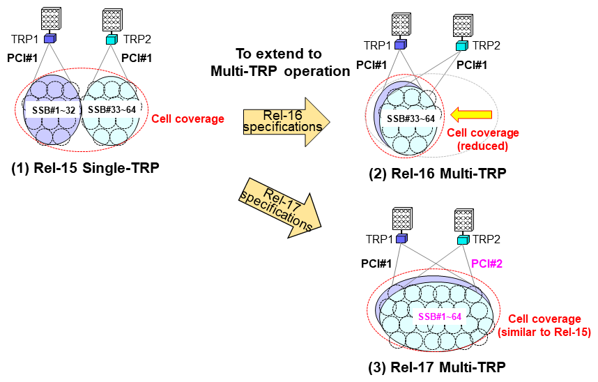
Figure 1 Evolution from Single-TRP operation to Multi-TRP operation
Rel-17 thus specifies functions for coordinated PDSCH transmission using multi-TRP with different PCIs. In this case, one TRP can maximize cell coverage by transmitting up to 64 SSB beams such that each beam does not overlap in the coverage area, and another TRP can transmit up to another 64 SSB beams with a different PCI. This allows two TRPs to maintain coverage similar to Rel-15 even if they transmit overlapping SSB beams. This resolves the issue of Rel-16 multi-TRP operation in FR2 (Fig. 1(3)).
2) Beam Failure Recovery for Each TRP
For Beam Failure Recovery (BFR) specified in Rel-15/Rel-16, when the reception quality of a beam in the Physical Downlink Control CHannel (PDCCH)*17 falls below a prescribed value, the UE reports to the base station that beam failure has occurred and new beam information for the beam to be changed. This makes possible BFR with low latency. However, BFR specifications in Rel-15/Rel-16 assumed a single TRP. Thus, in a multi-TRP environment, when beam failure occurs at one of the TRPs, BFR cannot be carried out properly. Rel-17 therefore established specifications so that when beam failure occurs at least one of the TRPs in a multi-TRP environment, the UE sends a request for BFR for the TRP in question and reports new beam information for the beam(s) to be changed for one or both of the TRPs (Figure 2). This enables low-latency recovery from beam failures at each TRP even in a Multi-TRP environment.
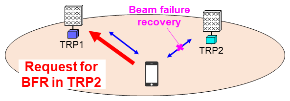
Figure 2 Beam failure recovery for each TRP
3) Inter-cell Mobility Using Layer 1/Layer 2 (L1/L2)*18 Beam Indication
A UE near the edge of a cell may temporarily have higher reception quality from another cell than its serving cell.*19 In Rel-15/Rel-16, if reception quality from another cell is higher than from the serving cell for a certain period of time, a handover*20 is performed to switch the serving cell to the other cell. However, handover interruption time*21 is incurred as a result, so frequent handovers are undesirable. Rel-17 therefore extends beam management using L1/L2 to allow the UE to transmit and receive signals from another cell while remaining connected to the serving cell (Figure 3)
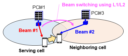
Figure 3 Inter-cell mobility using L1/L2 beam indication
The UE measures the SSB or Channel State Information-Reference Signal (CSI-RS)*22 of both the serving cell and neighboring cell. It reports the resource number of either the SSB or CSI-RS with the greater received power to the base station with an L1 beam report. In accordance with the extended beam indication mechanism, when the base station indicates the neighboring cell's beam to the UE, the UE transmits and receives user data in the indicated beam. Because handover is not performed with this function, there is no handover interruption time. This scheme allows UE to transmit and receive signals to/from the gNB node of another cell when the received power of that cell is temporarily greater than the received power of the serving cell. The received power of the transmitted and received signals and user throughput can thus be improved.
2.2 Frequency Expansion to 52.6 - 71 GHz Band
Rel-15 defined FR1 (0.41 - 7.125 GHz) and FR2 (24.25 - 52.6 GHz) as frequency ranges usable for NR. To increase further communication throughput and capacity, Rel-17 specified the new 52.6 - 71 GHz frequency band. Technologies needed for NR operation in this frequency band were provided based on Rel-15 and Rel-16 specifications. The specifications were also set in response to circumstances outside 3GPP. These included the completion of IEEE 802.11ay*23 standardization, which uses the 57 - 66 GHz band, in July 2021, and the identification at World Radiocommunication Conference (WRC)*24-19 of new 66-71 GHz band for International Mobile Telecommunication (IMT)*25 frequencies.
1) Issues in Use of 52.6 - 71 GHz Band
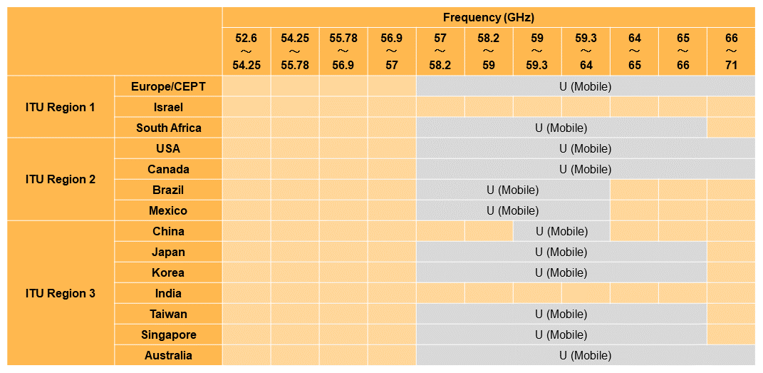
Enabling various operational modes using the 52.6 - 71 GHz band is required to achieve greater communication throughput and capacity in many cases. Thus, in addition to CA/DC operation with conventional lower frequency band, StandAlone operation (SA)*26 using the 52.6 - 71 GHz band only is also assumed. However, several issues must be resolved in order to support the operation in the new frequency range. For example, compared with sub-52.6 GHz frequencies, the 52.6 - 71 GHz band has greater phase noise*27 and propagation loss*28. Also, since unlicensed bands*29 are included in the 52.6 - 71 GHz frequency range (Table 1) [2], operation in such unlicensed bands must comply with regional regulatory requirements. Rel-17 supports the following specifications to address these issues.
Table 1 Licensing situation for various countries between 52.6 GHz and 71 GHz frequencies
2) Waveform*30, Subcarrier Spacing*31 and Bandwidth in 52.6 - 71 GHz Band
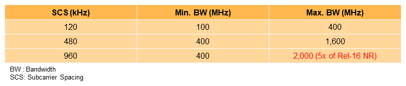
For waveform, as with NR in FR1/FR2, in the 52.6 - 71 GHz band Cyclic Prefix-Orthogonal Frequency Division Multiplexing (CP-OFDM)*32 and Discrete Fourier Transform Spread (DFTS)-OFDM*33 (UL only) are supported. For subcarrier spacing (SCS), in addition to 120 kHz already supported in Rel-15 FR2, 480 and 960 kHz are newly supported in the 52.6 - 71 GHz band. The following two points are thus achieved: (1) the effects of phase noise, an issue in using the new frequency range, can be reduced, and (2) the transmission bandwidth can be expanded without increasing the number of Fast Fourier Transform (FFT)*34 points during signal processing.
The maximum and minimum bandwidths are defined for each SCS, as shown in Table 2. In particular, a maximum bandwidth of 2 GHz per component carrier*35 is supported when 960 kHz is configured as the SCS. As this is almost the same bandwidth per channel as 11ay, communication capacity similar to 11ay is achieved.
Table 2 Minimum and maximum channel bandwidths in 52.6 - 71 GHz
3) Channel Access Mechanisms for Unlicensed Bands
(a) Type 1 - 3 channel access
In Europe and Japan, the Listen Before Talk (LBT)*36 protocol must be performed before transmitting on an unlicensed band in the 52.6 - 71 GHz frequency range, as is the case also when using unlicensed bands in the 5 GHz range. On the other hand, in other regions it is not necessary to perform LBT before transmitting on an unlicensed band in the 52.6 - 71 GHz frequency range. Based on these considerations, Rel-17 supports three types of channel access, Type 1 to Type 3, for 52.6 - 71 GHz band operations (Figure 4).
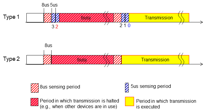
Figure 4 Channel access types for unlicensed bands in 52.6 - 71 GHz band
Type 1 channel access applies LBT in compliance with European regulations [3]. It uses a variable sensing period based on random backoff*37. Type 2 is not based on random backoff and has a fixed sensing period, which is intended to minimize the degradation in resource utilization efficiency due to LBT operation, while taking into consideration Japanese regulations and coexistence with other systems in other regions. Like licensed band access, Type 3 channel access performs transmission without sensing. It is intended for use in regions besides Europe and Japan. It can be used in Europe when certain requirements are satisfied.
(b) Use of narrow beam for LBT
For the receive beam*38 used during LBT in channel access as described above, using a narrow beam in accordance with beamforming*39, which is already supported in NR, can improve the sensitivity of interference detection. In the 52.6 - 71 GHz band, because propagation loss of radio waves is great, it is assumed that beamforming is applied for both transmission and reception. In contrast, LBT that uses an omni-directional receive beam without directivity gain may be insufficient for detecting and measuring channel interference, which may cause higher possibility of collisions with surrounding communications when data transmission begins even after LBT.
4) Initial Access Mechanism in 52.6-71 GHz Band
For SSB and the Physical Random Access CHannel (PRACH)*40, as with other signals and channels, SCS of 480 kHz and 960 kHz is supported. Similar to FR2, in the 52.6 - 71 GHz band, transmission of up to 64 SSBs in one SSB burst*41 using different beams is supported, where beam switching between two consecutive SSBs is assumed. However, when configuring 480/960 kHz SCS, compared with 120 kHz SCS, the CP length of each OFDM symbol*42 becomes shorter as the symbol duration is shortened. It is pointed out that such shortened CP length may not be sufficient to accommodate the time required for beam switching between consecutive SSBs, which may lead to degradation of SSB transmission quality.
A time-domain placement optimization for SSB transmission using wide subcarrier spacing is therefore supported (Figure 5). When 120 kHz SCS is used, two SSBs are placed consecutively in time. In contrast, when 480 kHz or 960 kHz SCS is used, a guard period*43 of three OFDM symbols is inserted between two SSBs in one slot.
5) Control Channels in 52.6 - 71 GHz Band
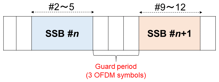
Figure 5 OFDM symbol for SSB when 480/960 kHz subcarrier spacing is configured
The most important issue concerning PDCCH was how to avoid an increase in load related to blind decoding*44 of PDCCH at UE when SCS of 480/960 kHz is configured. When SCS of 480/960 kHz is configured, compared with 120 kHz SCS, the slot length becomes 1/4 or 1/8, respectively. As a result, the load on the UE for PDCCH blind decoding is expected to be 4x or 8x when SCS is 480 or 960 kHz, respectively. Meanwhile, if the maximum number of PDCCH blind decoding and the resource amount per slot are simply reduced, it is pointed out that flexibility in configurations of PDCCH resources would be limited.
As a result of taking these points into consideration, for receiving PDCCH when 480 or 960 kHz SCS is configured, the following manner for PDCCH blind decoding for UE is supported: consecutive X slots are considered one group and PDCCH is received only in Y consecutive slots, which are included in this X slot group (Figure 6). X is 4 when 480 kHz SCS is configured, and 4 or 8 when 960 kHz SCS is configured. Y is 1 or X/2 for both 480 and 960 kHz SCS. As a result, the load related to blind decoding of PDCCH can be maintained to the same extent as when 120 kHz SCS is configured. At the same time, with regard to flexibility on PDCCH resource configuration, the same extent as when 120 kHz subcarrier spacing is set can be achieved within Y slots.
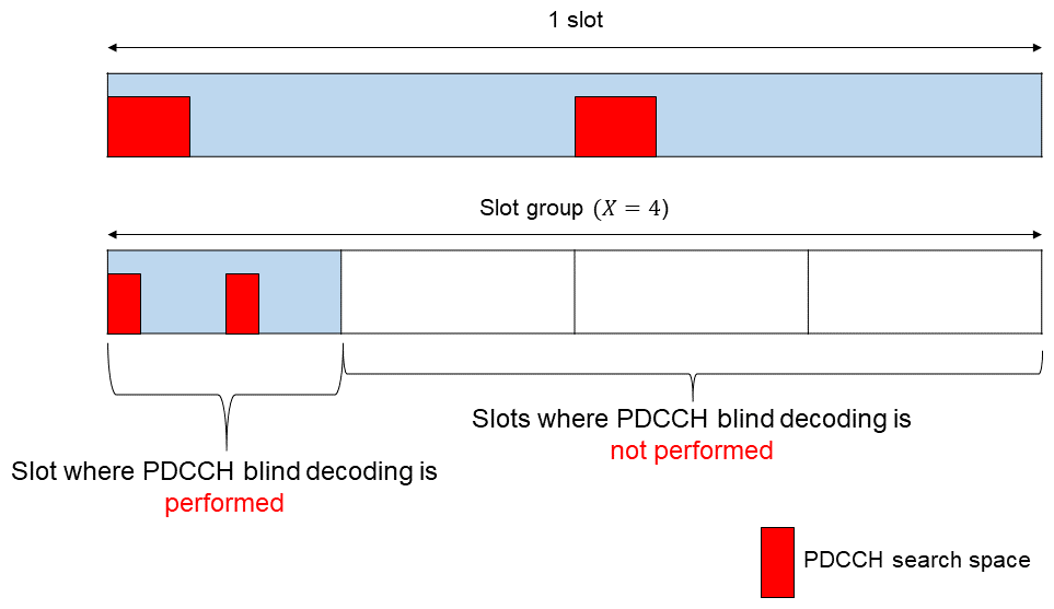
Figure 6 Example of PDCCH decoding in 52.6 - 71 GHz band when (top) 120kHz and (bottom) 480 kHz are configured.
6) Scheduling and Hybrid Automatic Repeat reQuest (HARQ)*45 in 52.6 - 71 GHz Band
With regard to scheduling, as described above, because the amount of blind PDCCH decoding in time domain becomes less when 480 and 960 kHz SCS is configured, it was observed that schedule efficiency needs to be improved in time domain. Therefore, the technique for scheduling multiple Physical Uplink Shared CHannels (PUSCH)*46 with one PDCCH, specified in Rel-16, was extended to PDSCH scheduling also. This supports scheduling multiple PDSCH or PUSCH (up to eight) with one PDCCH in time domain (Figure 7). Efficient scheduling of uplink and downlink data is thus possible even based on PDCCH blind decoding when 480 and 960 kHz SCS is configured.
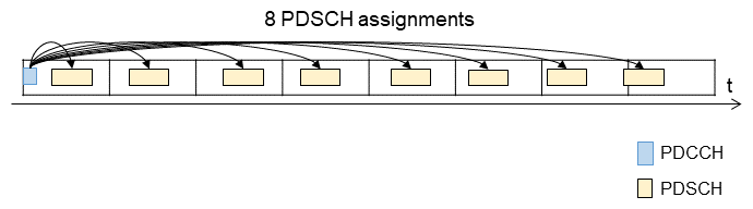
Figure 7 Example of multiple data transmission scheduling with one PDCCH
7) Definition of Frequency Range in 52.6 - 71 GHz Band and Base Station and UE Radio Frequencies (RF) Requirements*47
(a) Definition of frequency range in 52.6 - 71 GHz band
In Rel-15, two frequency ranges, FR1 and FR2, were defined, as follows.
- FR1: 410 - 7,125 MHz
- FR2: 24,250 - 52,600 MHz
In Rel-17, taking into consideration the expectations for the global utilization of 5G and the need to achieve further high-throughput data communication, a new frequency band from 52.6 to 71 GHz was discussed. To maximize use of existing FR2 base stations and UE's RF implementation, 3GPP extended the upper limit of the definition of FR2 from 52.6 GHz to 71 GHz. Along with this, the existing FR2 band is defined as FR2-1 and the newly expanded FR2 band is defined as FR2-2, as shown below (Figure 8).
- FR2-1: 24,250 - 52,600 MHz
- FR2-2: 52,600 - 71,000 MHz
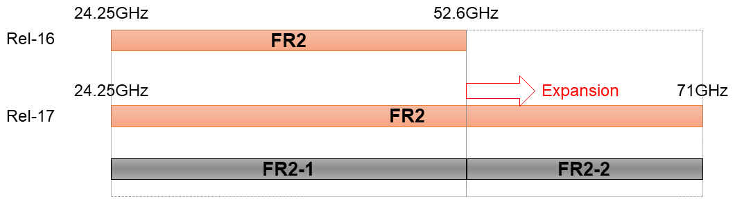
Figure 8 Expansion of FR2 with new frequency range
(b) RF requirements for base station and UE in 52.6 - 71 GHz band
For RF requirements on the base station side, 480 kHz and 960 kHz SCS have been added and the maximum bandwidth has been extended up to 2 GHz. Along with this, RF requirements to meet these new features have been specified, where the ones previously specified for FR2-1 were considered as baseline. For example, the Adjacent Channel Leakage Ratio (ACLR)*48 and Adjacent Channel Selectivity (ACS)*49 were studied for FR2-2. After a detailed review of the study conditions for FR2-2, requirements were set forth in 3GPP using previous simulation results. These simulations examined the effects of interference between radio base station equipment in the 70 GHz band and UE or radio base station equipment in adjacent frequencies (coexistence study).
For RF requirements on the UE side, in principle previous requirements are applied. However, a concern was that if application of the previous approach of considering RF requirements is applied to the FR2-2 band, it would result in reduced cell coverage due to propagation loss, which is assumed to be higher in the FR2-2 band. We thus conducted a technical study of antenna elements in the FR2-2 band. We reviewed the antenna element configuration while taking into account the expectation that the number of elements could be increased as the frequency increases due to the smaller space required between antenna elements. At 3GPP standardization meetings, we proposed increasing the assumed number of antenna elements in UE from four elements in FR2-1 to eight elements in FR2-2. The proposal was agreed upon, which resulted in improved cell coverage in the FR2-2 band while maintaining technological feasibility.
2.3 MR-DC Technology Enhancements
In Rel-16, MR-DC/CA technology enhancements were specified. It introduced functions such as highly efficient and low-latency MR-DC configuration and recovery, fast NR Secondary Cell (SCell)*50 activation, and fast Master Cell Group (MCG)*51 link recovery. In Rel-17, the following functions were added to further reduce MR-DC/CA processing latency and UE power consumption: (1) Secondary Cell Group (SCG)*52 deactivation, (2) improving the reliability and robustness of Primary Secondary Cell (PSCell)*53 addition/change, and (3) fast activation of SCell using temporary RS*54.
1) SCG Deactivation
Prior to Rel-17, the UE in MR-DC had to constantly maintain radio links*55 to both MCG and SCG. This resulted in the issue of increased power consumption by the UE and the network.
To address this issue, Rel-17 specified allowing the SCG to transition to deactivation state (to be deactivated) when the traffic can be handled without requiring the SCG link. In the SCG deactivated state, the UE does not send or receive data through the SCG, and measurement of the quality of the physical layer*56 of cells in SCG can be omitted depending on the configuration. As a result, it is expected that power consumption by the UE and the network would be reduced compared to the SCG activation state. In the SCG deactivated state, the UE also retains the settings for the deactivated SCG and the bearer*57 for the SCG. When the SCG is reactivated, these settings can be reused. Thus the procedures required for SCG configuration and SCG bearer establishment can be omitted. In contrast, when SCG is released, SCG configuration and Radio Link Control (RLC)*58 bearer are also released. Thus it is expected that when previously deactivated SCG is activated, SCG communication will restart faster than when a released SGC is added again, considering that SCG configuration and RLC bearer were also released.
When reactivating the SCG, if synchronization with the SCG is maintained, in other words, if no beam failure on the PSCell of the SCG is detected for a specified number of times during SCG deactivated state, and the Timing Advance (TA)*59 timer associated with the Primary Timing Advance Group (PTAG)*60 of the SCG has not expired, the UE can omit Random Access (RA)*61. This results in faster SCG reactivation.
2) Improving Reliability and Robustness in Addition and Changes of PSCells
In Rel-16, to improve reliability and robustness in handover and PSCell change*62, Conditional HandOver (CHO)*63 and Conditional PSCell Change (CPC) were specified. However, in Rel-16 CPC can only begin in a Secondary Node (SN), and only PSCells in the same SN that does not involve the Master Node (MN)*64 can be set as the target cell. Applicable scenarios are thus limited. In Rel-17, CPC scenarios and the functionality of PSCell change are enhanced.
In Rel-17, CPC can be initiated from either the MN or SN.
As an example of CPC in Rel-17, Figure 9 shows the operation of CPC between different SNs, initiated by the MN.
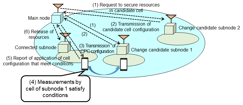
Figure 9 Example of operation of CPC between different subnodes
- The node that initiates CPC requests the SN to which the candidate target cell belongs to reserve resources.
- The SN that receives the request determines whether or not it can reserve resources. If so, it transmits the configuration list of cells that can secure resources to the MN.
- The MN transmits CPC configuration to the UE. The configuration includes a list of candidate cells and conditions for executing PSCell change to the candidate cells. An example of a condition for executing PSCell change is communication quality, e.g., a certain level higher than at the cell to which the candidate cell is connected.
- The UE receives the CPC configuration and performs measurements. If any candidate cell satisfies the CPC execution conditions, it changes the PSCell to that candidate cell.
- The UE indicates to the MN that CPC is applied and the cell to which CPC is applied.
- The MN starts resource release procedures for the SN to which the PSCell belonged prior to the change.
In addition to the new CPC described above, in Rel-17, Conditional PScell Addition (CPA) was specified. Like CPC, CPA sets multiple candidate cells and execution conditions when DC starts; in short, when a PSCell is added. Because the UE can perform fast PSCell addition/change based on the latest measurement results, CPC and CPA can improve reliability and robustness in an environment where communication quality changes rapidly, such as when FR2 is used.
Based on the expansion of scenarios in Rel-17, the coexistence of CHO, CPC, and CPA was also discussed. In Rel-17, while allowing simultaneous settings of each of these functions to be set in the UE, when any one of the functions meets conditions and its settings are applied by the UE, the settings of the other functions are released.
3) Fast Activation of SCell Using Temporary RS
For enhancement of the MR-DC technology in Rel-16, a point of concern was the length of time required for Channel State Information (CSI)*65 measurements and Automatic Gain Control (AGC)*66 when activating an SCell in deactivated state. Thus a new state, dormancy, in between deactivated and activated state, is defined to enable CSI measurements and AGC for an SCell in dormant state without changing it to activation state.
In Rel-17, for fast activation of a deactivated SCell, activation of the SCell using temporary RS was specified. In the Medium Access Control (MAC)*67 layer in the Rel-17 MR-DC extension, a new MAC Control Element (CE)*68 was introduced. In the previous SCell activation scheme, there is a need to wait for the periodically transmitted SSB to arrive and then receive CSI-RS after the UE receives the MAC CE. On the other hand, in the new SCell activation scheme, the base station transmits the MAC CE and then immediately a temporary RS. The UE that receives the MAC CE then uses the designated temporary RS for CSI measurement and AGC. Therefore, faster SCell activation without the need to wait for periodically transmitted SSB to arrive is expected.
2.4 Carrier Aggregation of FR2 Bands
For carrier aggregation in the FR2 band, which was newly introduced in 5G, Rel-16 specified carrier aggregation that bundles two frequency bands, 28 GHz and 40 GHz, for DL. In Rel-17, carrier aggregation for DL that bundles bands in the 28GHz range or bands in the 40GHz range is specified, expanding CA to support more frequency band combinations.
In addition, UL carrier aggregation that bundles 2GHz and 40 GHz bands is also specified to achieve wider bandwidth for UL. In 3GPP, we have promoted carrier aggregation specifications that bundle allocated 28 GHz and 40 GHz bands, taking into consideration the fact that the 40 GHz band is being studied for additional frequency allocation within Japan. This technology is expected to further increase UL throughput when the 40 GHz band is allocated in the future (Figure 10).
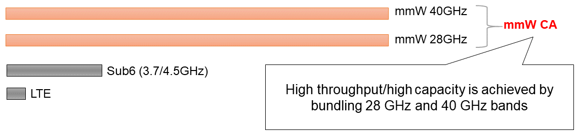
Figure 10 Carrier aggregation bundling 28GHz and 40GHz bands
- TRP: A set of one or more transmitter/receiver antenna ports installed at a single location in a base station. A base station configuration that uses only one transmitter/receiver antenna port at a single location is called a single TRP, while a base station configuration that uses multiple transmitter/receiver antenna ports at multiple locations is called multi-TRP.
- PDSCH: A physical channel for transmitting user data and control information from the higher layer signaling.
- MIMO layer: A single transmission system using different frequencies in the uplink and downlink.
- Single-user MIMO: Technology that uses MIMO transmission at identical temporal frequencies for a single user.
- Distributed MIMO: A MIMO transmission technology that transmits different MIMO streams from multiple base stations to a single mobile station.
- PCI: An identifier for a physical cell. In LTE 504 PCIs are available and reused.
- FR2: 24.25 - 52.6 GHz frequency range. A frequency band specified in 3GPP ranging from 24,250 to 52,600 MHz.
- SSB: Synchronization signal for detecting cell frequencies and timing required for communication and broadcast channel notifying of main radio parameters. Sent periodically by base stations.
- PDCCH: Control channel for the physical layer in the downlink.
- L1/L2: Layers in the Open Systems Interconnection (OSI) reference model. Layer 1 is the physical layer and Layer 2 is the data link layer.
- Serving cell: The cell where the UE currently has established a radio link.
- Handover: Switching of the serving cell to which the UE is connected.
- Handover Interruption Time: The period during a handover when the UE cannot send or receive user data to or from the base station.
- CSI-RS: A downlink reference signal used by the UE to measure the state of the radio channel.
- IEEE 802.11ay: A wireless LAN standard developed by the IEEE, based on the 5 GHz wireless LAN standard with additional extensions for high-frequency band use. Successor to 802.11ad (also known as WiGig).
- WRC: Held every three to four years.
- IMT: A generic term for international mobile communications systems standardized at ITU encompassing IMT-2000 (3G), IMT-Advanced (4G/LTE), IMT-2020 (5G), etc.
- Standalone: A deployment scenario using only NR, in contrast with non-standalone operation which uses LTE-NR DC to coordinate existing LTE/LTE-Advanced and NR.
- Phase noise: Phase fluctuations caused by frequency components other than the carrier frequency in the locally transmitted signal.
- Propagation loss: The amount of attenuation in the power of a signal emitted from a transmitting station until it arrives at a reception point.
- Unlicensed band: Frequency band that does not require a license to operate.
- Waveform: Transmission waveform used during signal transmission.
- Subcarrier spacing: Spacing between individual carrier waves transmitting signals in multi-carrier transmission such as OFDM.
- CP-OFDM: Orthogonal Wave Frequency Division Multiplexing with Cyclic Prefix (CP) insertion.
- DFTS-OFDM: Discrete Fourier Transform (DFT) processing of the signal before Inverse Fast Fourier Transform (IFFT) processing in CP-OFDM.
- FFT: A fast algorithm that transforms discrete data in the time direction into discrete data in the frequency domain.
- Component carrier: A carrier treated as a single frequency block having a maximum bandwidth of 20 MHz in LTE and a maximum bandwidth of 100 MHz and 400 MHz in FR1 and FR2, respectively, in NR.
- LBT: Mechanism to check in advance whether other devices are transmitting data before a device transmits data over the radio network.
- Random backoff: Technique to prevent multiple transmissions from occurring simultaneously and causing collisions by setting random LBT duration.
- Receive beam: A receiving operation in which beamforming is also applied during reception to increase/decrease the power of signals arriving from a particular direction.
- Beamforming: A technology that gives directionality to a transmitted signal, increasing or decreasing the signal power in a particular direction. Analog beam forming works by controlling the phase in multiple antenna elements (RF devices) to create.
- PRACH: Physical channel for transmission when the UE establishes a connection with a cell, for example, for initial access or handover.
- Burst: Temporally successive transmissions based on one LBT.
- OFDM symbol: A unit of transmission data consisting of multiple subcarriers. A Cyclic Prefix (CP) is inserted at the front of each symbol.
- Guard period: Time period set aside when the TDD system is used. It prevents downlink and uplink signals from colliding due to propagation delay.
- Blind decoding: Attempt in decoding on all resources from which a signal may be transmitted.
- HARQ: An error correction technique that combines high-rate channel coding and automatic repeat request (ARQ).
- PUSCH: Physical channel used for sending and receiving data packets in the uplink.
- RF requirements: Specification of characteristics related to the radio part, such as unwanted emissions limits and receiver sensitivity.
- ACLR: In modulated signal transmission, the ratio between the transmitted signal band power and undesired power generated in the adjacent channels.
- ACS: The ability to correctly select and receive (i.e., filtering) the desired wave even under the condition that signal-power ratios of the desired wave and an interfering wave adjacent to the desired wave are prescribed.
- SCell: A carrier that is not the carrier that maintains the connection (PCell) among the multiple carriers used in CA.
- MCG: A cell group under a base station (Master Node (MN)) that establishes a connection with the UE in DC.
- SCG: A cell group under non-MN base station (Secondary Node (SN) from among the base stations in DC.
- PSCell: Of the cells included in the SCG in DC, the cell in CG that maintains the connection.
- Temporary RS: Reference signal specified in MAC CE (see *68) that indicates rapid SCell activation.
- Radio link: A logical link between the UE and cells (access points in a radio access network).
- Physical layer: The layer that performs modulation of radio frequency carriers and coded data modulation for radio signal transmission.
- Bearer: The path to transfer user data packets.
- RLC: A Layer 2 sublayer of the radio interface and a protocol that performs services such as retransmission control.
- TA: The amount of timing adjustment on the UE side to maintain signal orthogonality between multiple UEs.
- PTAG: Of the TAGs, the TAG that includes the PCell or PSCell. A TAG groups TAs when different TAs (see *60) are required for each carrier during CA.
- RA: A procedure performed when the UE establishes a connection with the base station or resynchronizes with the base station at the time of an outgoing call or handover.
- PSCell change: Operation to change the PSCell to which the UE is connected.
- CHO: Operation in which the UE sets candidate cells for handover and handover execution conditions. When the execution conditions are met, the UE performs the handover autonomously.
- MN: A base station that establishes an RRC connection with the UE in DC. In MR-DC, the MN can be an LTE base station (eNB) or NR base station (gNB).
- CSI: State of the radio channel between the base station and the UE.
- AGC: Control to suppress fluctuations in received signal strength and maintain it at a constant level.
- MAC: A sublayer of Layer 2. A protocol that performs functions such as radio resource allocation, mapping data to TBs (see *80), and HARQ retransmission control.
- MAC CE: A particular configuration control signal transmitted on the MAC sublayer.
-
3.1 Coverage Enhancement for Physical Channels
Open
A radio communication system's coverage performance is one of the most critical elements in 5G service because it impacts the density of base stations deployment and costs needed to provide the service area, stability of UE's network connections, and the quality of the user experience. Because NR uses high-frequency bands that are more linear and which increase in propagation loss occurs easily, coverage performance degradation is a point of concern.
In 3GPP, evaluation of FR1 coverage performance based on Rel-15 specifications has been conducted. However, evaluation based on Rel-16 specifications and evaluation of FR2 has not yet been conducted. For Rel-17, evaluation of FR1 and FR2 coverage performance based on Rel-16 specifications were carried out to identify signals and channels that need improvement and specify coverage enhancement techniques.
1) Identification of Signals and Channels Requiring Improved Coverage Performance
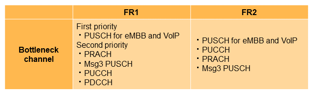
For a Rel-17 coverage enhancement Study Item*69, Link Level Simulation (LLS)*70 was used to study signals and channels that require coverage performance in FR1 and FR2. The scenarios, frequencies, services, and target data rate used in the study are shown in Table 3. In order to evaluate how these requirements can be met, LLS simulation assumptions were determined, and Signal to Interference plus Noise power Ratio (SINR)*71 obtained from simulation was used to calculate the link budget*72. Channels that exceed the acceptable propagation loss*73 to achieve a specific Inter-Site Distance (ISD)*74 were then identified as bottleneck channels, as shown in Table 4 [4]. As a result, in FR1, PUSCH, which was identified as a bottleneck channel in many scenarios and for many frequencies and services, and which required a large amount of improvement, was given top priority.
Table 3 Scenarios, frequencies, services, packet sizes, and target transmission throughputs used to evaluate coverage performance
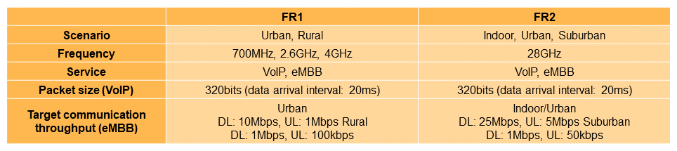
Table 4 Bottleneck channels
2) Coverage Enhancement Techniques
Of the bottleneck channels identified in the Study Item, those that demanded performance improvement in more scenarios and services, and signals and channels that required significant improvement, were selected. Enhancement techniques for them were defined in Work Items*75.
(a) Enhancement of PUSCH repetition type A*76
In Rel-15, PUSCH repetition type A is specified. PUSCH repetition is transmitted for each slot to improve the base station's reception SNR. Because the number of repetitions is set for consecutive slots, not only UL slots but DL slots are counted in the number of PUSCH transmissions in Time Division Duplex (TDD)*77. PUSCH transmissions that collide with DL slots are cancelled. This results in the issue of the reduction of the effective number of repetitions. Rel-17 therefore specifies the following two functions to increase the effective number of repetitions.
- Increase in maximum number of repetitions
The maximum number of PUSCH repetition is eight in Rel-15 and 16 in Rel-16. It has been extended to 32 in Rel-17. - Repetition based on available UL slot*78
In Rel-15/Rel-16, the number of PUSCH repetition is counted as PUSCH transmissions even for DL slots in TDD. Rel-17 therefore expanded the repetition counting so that it also applies PUSCH transmissions to available UL slots. The number of actually set repetition can be carried out even when DL slots exist in the middle of repetition.
(b) Transport Block (TB)*79 transmission over multiple PUSCH slots (TB processing over Multiple Slots (TBoMS))
In Rel-15/Rel-16, the Transport Block Size (TBS) of the UL data transmitted by PUSCH is calculated based on factors such as the number of Resource Elements (RE)*80 available for PUSCH in the allocated slot. Assuming a mobile station at the edge of the service area, it is believed that low error-rate PUSCH transmission can be achieved by using low Modulation and Coding Scheme (MCS)*81 and a small number of Physical Resource Blocks (PRB)*82 to increase the Power Spectrum Density (PSD)*83, in addition to PUSCH repetition (Figure 11(a)). On the other hand, with such a transmission method, the size of data that can be transmitted within a slot is reduced. As a result, there is a need to transmit TBS data in small pieces, as shown in Fig. 11(b). This is inefficient in terms of coding gain.
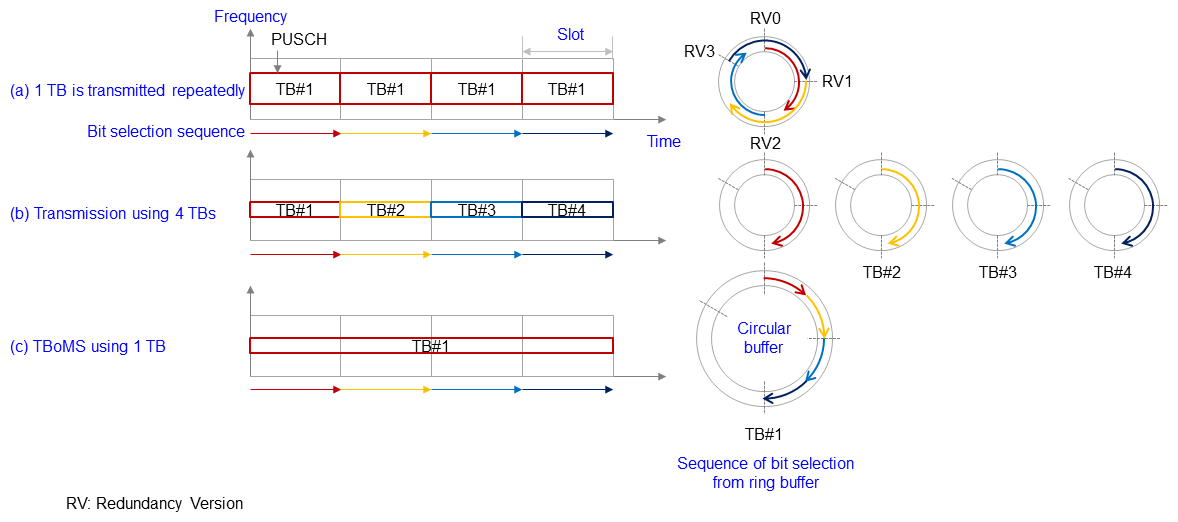
Figure 11 Overview of PUSCH TB allocation and TBoMS
In order to resolve this issue, TBoMS that transmit one TB over multiple PUSCH slots is specified. This is done by calculating TBS based on the number of RE available to PUSCH within multiple slots and mapping a sequence of consecutive bit selections from a circular buffer to each slot (Fig. 11(c)). To achieve this, a new indication of the number of slots to which one TB is allocated is introduced. The mobile station calculates the TBS based on the number of slots indicated and transmits the TB over multiple slots.
(c) Bundling of reference signals for demodulation (DeModulation RS: DM-RS)*84 in PUSCH and Physical Uplink Control CHannels (PUCCH)*85
For mobile stations at the edge of the service area, channel estimation*86 accuracy is important to prevent degradation of communication characteristics due to channel estimation errors. In Rel-15/Rel-16, the channel estimation by the base station for scheduled PUSCH/PUCCH is carried out using DM-RS present in PUSCH/PUCCH resources.
In Rel-17, in order to improve channel estimation accuracy, DM-RS bundling is specified. When channel estimation is carried out for scheduled PUSCH/PUCCH, not only DM-RS present in those PUSCH/PUCCH resources but also DM-RS in other PUSCH/PUCCH resources are combined. To achieve this, Time Domain Window (TDW)*87 is introduced, and a nominal TDW*88 is set for multiple consecutive slots depending on the base station configuration or mobile station capabilities. As shown in Figure 12, within the range of the nominal TDW (Nominal1 TDW), the mobile station can set one or more actual TDW*89. The starting position and length of the actual TDW are determined based on e.g., the TDD's UL and DL slots and frequency hopping. By the mobile station's transmission of DM-RS in the actual TDW with constant power and phase continuity, the base station can perform channel estimation using DM-RS present in multiple PUSCH/PUCCH resources in the actual TDW.
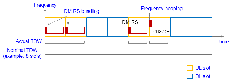
Figure 12 Overview of DM-RS bundling
(d) Message3 (Msg3)*90 PUSCH repetition
Rel-15/Rel-16 specifications do not allow repetition to be applied to Msg3 PUSCH used for initial access, etc. However, to improve coverage performance, it is effective to carry out not only PUSCH repetition in Radio Resource Control (RRC)*91 connection but also repetition of Msg3 PUSCH used for initial access.
Rel-17 therefore introduces repetition of Msg3 PUSCH up to eight times to improve the base station's reception SNR. The base station indicates to the mobile station the threshold value of the Reference Signal Received Power (RSRP)*92 to determine whether or not to request Msg3 PUSCH repetition. The mobile station can request repetition if the RSRP to be received is below the threshold value. The base station indicates to the mobile station the PRACH Preamble index*93 or PRACH occasion*94 that can be selected depending on whether or not a request is made. The mobile station selects the Preamble Index or PRACH occasion based on the existence of repetition request. The base station indicates the number of repetitions using the MCS field within the Random Access Response (RAR) UL grant,*95 which transmits Msg2*96 PDSCH in response to the mobile station's repetition request. At that time, the mobile station that requested repetition replaces the content of the MCS field and transmits Msg3 PUSCH with the indicated number of repetitions.
(e) Dynamic indication of number of repetitions in PUCCH
In Rel-15/Rel-16, the number of PUCCH repetition is commonly set for all PUCCH resources. In Rel-17, dynamic indication of the number of repetitions is introduced to appropriately set the number of repetitions based on the mobile station's communication environment. To realize this function, different number of repetitions can be set for each PUCCH resource. By indicating the PUCCH resource using the PUCCH Resource Indicator (PRI)*97 field in Downlink Control Information (DCI) *98 according to Rel-15/ Rel-16 operations, the number of PUCCH repetition can be dynamically indicated based on the factors such as the channel quality.
3.2 NR Repeater
As equipment for contributing to further coverage expansion of the 5G area, specifications for the NR Repeater were produced. The NR Repeater is an extension of the RF repeater for NR. The RF repeater amplifies and relays radio waves transmitted and received between radio base station equipment and the UE. In Japan, RF repeaters are used as low-power repeaters and land mobile relay stations that amplify and relay radio waves in blind areas such as indoor areas and mountainous regions. The development of RF repeaters for NR and establishment of regulations with these Rel-17 specifications are thus expected to further expand and increase the density of 5G areas when high-throughput communication is possible.
1) NR Repeater Study Conditions
The NR Repeater has a link facing the base station (uplink) and a link facing the UE (downlink) to amplify and relay radio waves transmitted and received between the radio base station equipment and the UE (Figure 13). For each link, the requirements for each radio characteristic were specified by studying the basic parameters of radio characteristics such as output power, frequency error*99, Adjacent Channel Leakage power Ratio (ACLR), and spurious*100 emissions.
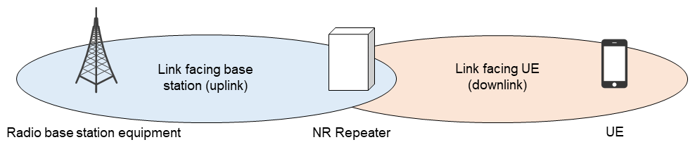
Figure 13 Image of each link in NR Repeater
Usually, when discussing requirements for radio characteristics, the effects of interference between the equipment to which requirements are to be applied and the UE or radio base station equipment that use adjacent frequencies are evaluated by simulation (co-existence study). However, for the NR Repeater, the study conditions are simplified in the following manner. The maximum output power is set so that for the link facing the base station, it is equivalent to the UE's maximum output power, and for the link facing the UE, it is equivalent to the radio base station equipment's maximum output power. Results of simulations related to the UE and radio base station equipment for 5G systems conducted by 3GPP in the past are reused.
The NR Repeater in Rel-17 was studied with the assumption that it only amplifies and relays radio waves without decoding or demodulating received signals. Therefore, since the NR Repeater does not recognize the content of signals received from the radio base station equipment, adaptive beamforming control, which sets an appropriate beam for each UE based on the control signal, is not assumed for the NR Repeater at this time. Only beamforming with a fixed beam shape in a specific direction is assumed. NR Repeater capable of adaptive beamforming based on the control signal from the base station is considered for Rel-18 as a Network-Controlled Repeater.
2) Expansion of Supported Frequencies
The NR Repeater further expands the supported frequency bands. LTE RF repeater supports Frequency Division Duplex (FDD) bands*101 up to 3,590 MHz only. On the other hand, of the total frequency bands specified for 5G radio base station equipment, NR Repeater in Rel-17 supports all FDD/TDD bands except unlicensed bands and the FR2-2 band mentioned above. Thus NR TDD bands, including the 3.7 GHz band (n77*102/n78), 4.5 GHz band (n79), and 28 GHz band (n257), which are used in Japan as frequency bands for 5G, can be newly used.
Note that when operating in TDD bands, the NR Repeater needs to synchronize with the radio base station and adjust the timing of transmitting and receiving signals to avoid interference with other network systems. The NR Repeater control in Rel-17 needed for synchronization with the radio base station and timing of transmitting and receiving signals is to be realized by each manufacturer's individual implementation. A unified implementation method has not been standardized in the specification.
3) Rearrangement of Equipment Configuration
With new extension of FR2 support, equipment configuration of the NR Repeater has been rearranged. For the FR1 band, requirements for each radio characteristic are specified based on a configuration (Repeater type 1-C) that assumes separation of the antenna for transmitting and receiving radiated radio waves and the radio part*103. For these requirements, measurement is carried out with the NR Repeater's physical antenna connector connected by wire to the measurement device.
For the FR2 band, on the other hand, because the power loss in circuits become great, requirements for each radio characteristic are specified assuming a configuration with integrated amplifier, filter, and antenna for transmitting and receiving (Repeater type 2-O). Because a physical antenna connector can be connected by wire is not implemented, each radio characteristic requirement is assessed with Over The Air (OTA)*104 measurements at points in propagation space.
3.3 FR1 High Power UE
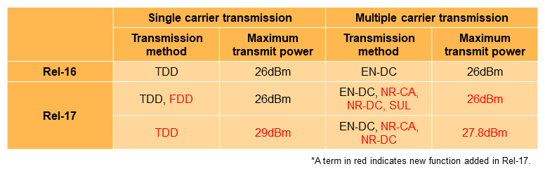
Technologies to increase the maximum UE transmit power (high power UE) are expected to expand UL coverage in FR1. In Rel-17, new functions were discussed and functions enhancing high power are introduced. These include technologies to increase up to twice the maximum UE transmit power specified prior to Rel-16 and to deploy high power UE functions in the FDD band (Table 5).
Table 5 Functional enhancements for high power UE in Rel-17
1) High Power UE in Single Carrier Transmission
Prior to Rel-16, for UE transmit power in single carrier transmission, the maximum output for handheld UE such as smartphones was specified as Power Class 3 with maximum of 23 dBm or Power Class 2 with maximum of 26dBm. To expand coverage in the future, Power Class 1.5, capable of transmitting twice the power (29 dBm) of Power Class 2, was introduced for n77, n78, and n79. While there are some limitations, such as setting an appropriate UL transmission ratio, this specification is expected to enhance UL coverage because it is based on existing radio protection guidelines.
UE transmit power in single-carrier transmission was previously limited to TDD bands. Rel-17 introduces UE transmit power in single-carrier transmission to FDD bands as well. FDD is a duplexing method that divides the frequency into transmitting and receiving bands and simultaneously carries out transmit and receive operations. However, because of the effects of interference from the UE's own transmission bands, specifications were introduced to take into account the amount of degradation in receiver sensitivity as transmit power increases.
2) High Power UE in Multi-carrier Transmission
For UE transmit power in carrier aggregation, where multiple transmission carriers are bundled, prior to Rel-16 only high power UE was applied to Evolved Universal Terrestrial Radio Access Network New Radio Dual Connectivity (EN-DC)*105. However, in Rel-17, the target scenarios are expanded to NR-CA, NR-DC*106, and Supplementary UpLink (SUL)*107. This makes it possible to use high power UE in a wide range of use cases.
In addition, prior to Rel-16, the total power of multi-carrier transmission was limited to 26 dBm. Rel-17 introduces a new function that raises the total power from the previous limit to the sum of the maximum output power of each band. Thus each band's power amplifier output can be used to its maximum limit. For example, with two power amplifiers, one capable of outputting 23 dBm transmit power and the other 26 dBm transmit power, previously the total transmit power was limited to 26 dBm. With the new function, each power amplifier to be operated at its maximum output power, resulting in transmit power of 23dBm+26dBm=27.8dBm. The new function is thus expected to expand coverage in carrier aggregation.
- Study Item: A task in 3GPP to examine an issue in order to develop specifications.
- LLS: Simulation to evaluate communication characteristics and performance between a base station and mobile station by modeling the functions of the base station and UE and the propagation characteristics of radio transmission paths.
- SINR: Ratio of desired received signal power to that of other received signals (interfering signals from other cells or sectors and thermal noise).
- Link budget: A design criterion for the allocation of average power levels between the base stations and mobile UEs. This is used for calculating cell radius from various wireless parameters such as transmitter power, frequency and receiver sensitivity.
- Propagation loss: Loss in the propagation path estimated from the difference between the transmit power and the receive power.
- ISD: Distance between base stations.
- Work Item: A task in 3GPP to set forth specifications.
- PUSCH repetition type A: Repeated transmission of PUSCH at every slot as specified in Rel-15.
- TDD: A bidirectional communications mode in which different time slots are allocated to uplink and downlink communications using the same frequency.
- Available UL slot: UL slot that allows the transmission of PUSCH or PUCCH.
- TB: A basic unit used when processing data transmissions, etc.
- RE: A component of the downlink resource composed of one subcarrier and one OFDM symbol.
- MCS: Combinations of modulation scheme and coding rate decided on beforehand when performing Adaptive Modulation and Coding (AMC).
- PRB: A unit for allocating radio resources consisting of one subframe and 12 subcarriers.
- PSD: Power density of the signal with respect to frequency.
- DM-RS: A reference signal used for channel estimation, used for decoding data transmitted on the uplink and downlink.
- PUCCH: The physical channel used to send and receive Uplink Control Information (UCI).
- Channel estimation: The process of estimating the amount of fluctuation in received attenuation and phase rotation in the received signal when a signal is transmitted over a radio channel.
- TDW: Interval where the mobile station transmits the DM-RS with constant power and continuity phase for DM-RS bundling.
- Nominal TDW: Nominal TDW set by the base station.
- Actual TDW: Actual TDW determined based on UL and DL slots, frequency hopping, etc.
- Msg3: Information requesting a connection to the network, sent by a mobile station that receives Msg2 in the random access procedure.
- RRC: A Layer 3 protocol that controls radio resources in a radio network.
- RSRP: Received power of a signal measured at a receiver. RSRP is used as an indicator of receiver sensitivity in a terminal.
- Preamble index: Index assigned to the particular pattern of preambles sent by the UE.
- PRACH occasion: Transmission opportunity available for transmitting PRACH.
- RAR UL grant: Information such as the temporary identifier of the mobile station and the allocation of Msg3 transmission resources that the base station sends as a response when it detects a PRACH.
- Msg2: Information such as the temporary identifier of the mobile station and allocation of Msg3 transmission resource, sent as a response when the base station detects a PRACH in the random access procedure.
- PRI: Information that indicates the PUCCH resource to be used from among multiple PUCCH resources set by the base station.
- DCI: Control information transmitted on the downlink that includes scheduling information needed by each user to demodulate data and information on data modulation and channel coding rate.
- Frequency error: The deviation between the frequency specified by the equipment and the frequency actually transmitted (measured value), expressed as a ratio.
- Spurious: An unwanted wave emitted at a wavelength outside the channel bandwidth of the main signal when that signal is transmitted.
- FDD band: A method of transmitting signals by dividing the frequency between the uplink and downlink.
- n77, n78, n79: Frequency bands of the TDD system in the FR1 band. n77 refers to 3,300 - 4,200 MHz, n78 to 3,300 - 3,800 MHz, and n79 to 4,400 - 5,000 MHz.
- Radio part: Radio functional part that includes amplifiers, filters, duplexers, etc. for transmitting and receiving signals.
- OTA: A method of measuring the characteristics of radio waves transmitted by a repeater's antenna, which opposes the measurement antenna.
- EN-DC: A technology that achieves wideband communication by bundling the LTE frequency band with the NR frequency band.
- NR-CA refers to a communication scheme in which the NR frequency band and the NR frequency band are bundled and carrier aggregation is performed. When multiple NR frequency bands are connected to the same base station, it is called NR-CA. When they are connected to different base stations, they are called NR-DC.
- SUL: Frequency bands that are used only for uplink communications and the communication methods that use them.
-
To improve user experience, reduction of UE power ...
Open
To improve user experience, reduction of UE power consumption is also important as well as improving data rate and latency. In Rel-16, power saving technologies for connected-mode Discontinuous Reception (DRX),*108 were specified, which include the wake up signal*109 in connected-mode Discontinuous Reception (DRX),*110 adaptation of maximum number of MIMO layers, SCell dormancy*111, improvements in cross-slot scheduling*112, and UE assistance information. In Rel-17, to solve issues in particular use cases that cannot be solved by Rel-16 power saving technologies, e.g., UE power consumption in idle/inactive mode in NR SA operation and in connected mode in FR2, the following technologies are specified.
4.1 Reduction of UE Power Consumption in Connected Mode
The UE in idle/inactive mode in NR SA operation must monitor paging messages*113 at the paging occasion*114 every certain period. The time/frequency synchronization*115 and AGC must be performed before the paging occasion. When carrying this out, multiple reference signals are needed based on radio quality and other factors, and the UE may need to wake up every few tens of milliseconds, which is the SSB transmission cycle. Sufficient sleep time thus cannot be ensured during the SSB transmission cycle, and the UE transitions to light sleep, which is power-inefficient, instead of power-efficient deep sleep. This contributes to reduced power consumption efficiency. To address these issues, the following two functions were added to Rel-17.
1) Paging Early Indication (PEI)
Because the UE in idle/inactive mode does not know in advance if there is a self-addressed paging message in the paging occasion, it performs time/frequency synchronization and AGC necessary to receive the paging message described above, regardless of whether or not the message exists. At that time, if there is no actual sending of self-addressed paging message, the UE performs unnecessary operations. In Rel-17, paging early indication is carried out to indicate to the UE in advance about the existence of a paging message (Figure 14(a)). This function improves UE power consumption by reducing unnecessary time/frequency synchronization and AGC. Paging early indication allows indication of the existence of paging message for each of the UE's subgroups. Subgroups can be allocated by the Core Network (CN)*116 or the UE ID.
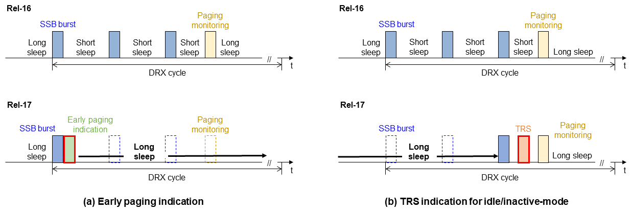
Figure 14 Reduction of UE power consumption in idle/inactive mode
2) Indication of Tracking Reference Signal (TRS)*117 in UE Idle/Inactive Mode
In Rel-16, TRS can be used only in the connected mode. In Rel-17, TRS-related information can be indicated by broadcast information*118 so that TRS can also be used in idle/inactive mode. As shown in Fig. 14(b), before the UE in idle/inactive mode receives paging, when multiple reference signals must be received in order to carry out time/frequency synchronization and AGC, in Rel-16 the UE must wake up for each SSB reception. In Rel-17, in addition to SSB for time/frequency synchronization and AGC, TRS is used. Compared with synchronization using only SSB, this allows the number of wake ups to be reduced. By using TRS indication for UE in connected mode and for UE in idle/inactive mode, UE power consumption can be reduced without increasing resource overhead.
4.2 Reduction of UE Power Consumption in Connected Mode
For reduction of UE power consumption in connected mode in FR2 operation, the following functions were added in Rel-17 to reduce downlink control signal (PDCCH) monitoring and relax physical link monitoring/BFR detection (beam failure detection) measurements.
1) Reduction of Downlink Control Signal Monitoring
In FR2 operation, because slot length becomes shorter, in general the number of downlink control signal monitoring per unit of time increases. Thus the following functions are introduced to reduce downlink control signal monitoring when no transmission or reception of user data is expected.
(a) Skipping of downlink control signal monitoring
The base station can indicate to the UE to skip downlink control signal monitoring for a specified period of time using Downlink Control Information (DCI). This function allows UE power consumption to be reduced by maintaining a sleep period for the UE (Figure 15(a)). For the configurable skip period, up to three skips for a period of up to 100 ms can be set in advance for the UE. Each skip indication can be specified with DCI from among the three skip periods.
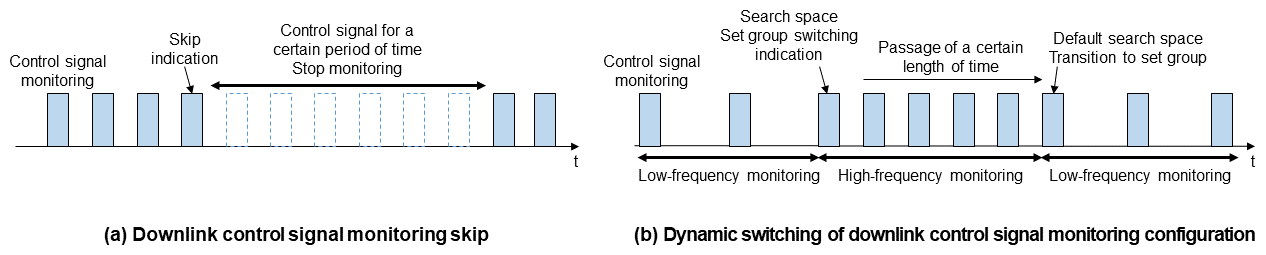
Figure 15 Reduction of UE power consumption in connected mode
(b) Dynamic switching of downlink control signal monitoring settings
The base station can indicate to the UE switching of the search space set group*119 using DCI. This makes possible dynamic switching of downlink control signal monitoring settings connected to the search space set group (Fig. 15(b)). For example, unnecessary downlink control signal monitoring can be reduced, resulting in reduced UE power consumption, by setting high-frequency or low-frequency monitoring period based on traffic conditions. Up to three search space set groups can be set, and group transition can be indicated by DCI between these three groups. If no downlink control signal accompanying data scheduling is received for a certain period of time, the UE transitions to the preset default search space set group.
2) Physical Link Monitoring/Relaxation of BFR Detection Measurement
In FR2 operation, physical link failures and beam switching may occur frequently because of small cell radius and the use of beamforming. Therefore, by relaxing provisions related to physical link monitoring and BFR detection measurements, power consumption can be reduced for UE moving at a low speed and UE with good reception quality.
- Connected mode DRX: A method to reduce UE power consumption by using intermittent reception of downstream control signals.
- Wake up signal: A signal that indicates in advance whether or not it is necessary to activate (wake up) the UE hardware, etc.
- Connected mode DRX: A method to reduce UE power consumption by using intermittent reception of downstream control signals.
- Dormancy: A state in which the UE power consumption can be reduced by not monitoring the PDCCH of the SCell. Fast return to activation state is possible by making necessary preparations for communication such as CSI measurement.
- Cross-slot scheduling: Method of scheduling a downstream control signal into a slot different from the slot in which it is received.
- Paging message: A signal used for calling a terminal in standby to establish a connection with the network.
- Paging occasion: Radio resource for receiving paging.
- Frequency synchronization: A state in which the clock frequencies between equipment match.
- CN: A network consisting of gateway equipment, location management equipment, subscriber information management equipment, etc. The core part of the network that constitutes a mobile communication system. Mobile equipment communicates with the core network via a radio access network consisting of radio base stations and other systems.
- TRS: Reference signal used mainly for synchronization processing.
- Broadcast information: Various types of information broadcast simultaneously by the mobile UE to each cell, such regulatory information, common channel information, and random access channel information, to execute connection procedures to the cells.
- Search space set group: A group containing a number of domains (search space sets) in which the UE attempts decoding of downlink control signals.
-
This article has described main functionalities of ...
Open
This article has described main functionalities of the Rel-17 NR specifications to achieve higher throughput, higher capacity, expanded coverage, and reduced UE power consumption. The use of Rel-17 NR functionalities, including those described in this article, is expected to further enhance user experience of 5G NR communication networks. NTT DOCOMO has contributed to the advancement of 5G standardization in 3GPP, and will continue to contribute to the further development of 5G standardization.
-
REFERENCES
Open
- [1] H. Harada et al.: “Advanced 5G Radio Technologies in 3GPP Release 17,” NTT DOCOMO Technical Journal, Vol. 24, No. 3, Apr. 2023.
https://www.docomo.ne.jp/english/corporate/technology/rd/technical_journal/bn/vol24_3/004.html - [2] 3GPP TR38.807 V16.1.0: “Study on requirements for NR beyond 52.6 GHz,” Apr.2021.
- [3] ETSI EN302 567 V2.2.1: “Multiple-Gigabit/s radio equipment operating in the 60 GHz band;Harmonized Standard for access to radio spectrum,” Jul.2021.
- [4] 3GPP TS38.830 V17.0.0: “Study on NR coverage enhancements,” Dec. 2020.
- [1] H. Harada et al.: “Advanced 5G Radio Technologies in 3GPP Release 17,” NTT DOCOMO Technical Journal, Vol. 24, No. 3, Apr. 2023.

