
Special Articles on 3GPP Release 17 Standardization Activities
Advanced Technologies for Industry Creation and Solution Co-creation in 3GPP Release 17
IoT NTN Network Slicing
Shinya Kumagai, Yuki Takahashi and Shohei Yoshioka
6G-IOWN Promotion Department
Shoki Inoue, Tianyang and Min
Radio Access Network Development Department
Masaya Okamura
Communication Device Development Department
Abstract
The use of 5G technology is being envisioned for various industrial fields beyond mobile communications, such as smart factories. 3GPP Rel-17 has added specifications targeting a much broader range of use cases and advanced solutions than Rel-16. This article describes radio access specifications in 3GPP Rel-17 that contribute to industry creation and solution co-creation.
01. Introduction
-
5th Generation mobile communications system (5G) technologies ...
Open

5th Generation mobile communications system (5G) technologies are being considered an important element supporting industrial development and solutions to diverse social issues, and Radio Access Network (RAN)*1 technology in particular is being studied for implementation of certain use cases and services. The 3rd Generation Partnership Project (3GPP) Release 17 specifications (Rel-17), further advance radio technologies for industry collaboration envisioned in Rel-16, and specify technologies that expand the domain of industry collaboration.
This article describes background to study of various solutions that mainly target industry collaboration for Rel-17, and radio technologies to implement those solutions.
- RAN: A network consisting of radio base stations and radio control equipment, situated between the core network and mobile terminals.
-
Industry-collaboration solutions related to ...
Open
Industry-collaboration solutions related to 3GPP Rel-17, with background and technical requirements, are summarized below.
2.1 Smart Factories
Smart factories are one type of industry-collaboration solution, in which all kinds of devices are connected one another within a factory to implement automation and control using highly reliable and low-latency wireless networks. Radio technologies for implementing such functions were already specified in Rel-16 [1], but study on smart factories was continued for Rel-17 to further increase reliability and reduce latency.
For example, for factory motion control and automation*2, Rel-16 and Rel-17 set a target of “transmission of a 20-byte packet in 2 ms or less with reliability of 99.9999% or better.” For deterministic communications*3, a target value of 1 µs or less was also set for clock synchronization accuracy. To implement smart factories, it is also necessary to be able to obtain accurate positioning data for equipment in real time [2]. However, since it is difficult to receive Global Navigation Satellite System (GNSS)*4 signals indoors, there is demand for highly accurate, low-latency positioning using Radio Access Technology (RAT)*5 signals, and the specification sets positioning accuracy targets of within 0.2 m horizontally and within 1 m vertically, with end-to-end latency of 100 ms or less. For cases with safety requirements, such as Automated Guided Vehicles (AGV)*6, the integrity of positioning is also specified, so that the reliability of positioning can be confirmed.
2.2 IoT
Earlier radio specifications for cellular communications have targeted advanced devices such as smartphones and industrial devices, and IoT devices such as sensors. For high-end IoT devices, radio specifications for enhanced Mobile BroadBand (eMBB) or Ultra-Reliable and Low Latency Communications (URLLC) were used, and low-end IoT devices were accommodated using LTE-IoT specifications such as Narrow Band-IoT (NB-IoT)*7 or enhanced Machine Type Communication (eMTC)*8. However, these radio and LTE-IoT specifications are not optimized for mid-range IoT devices, between the high-end and low-end devices, such as wireless sensors, video surveillance, and wearable devices, so there has been further study on radio specifications suited to mid-range IoT devices (Figure 1). Requirements for various use cases are shown in Figure 2.
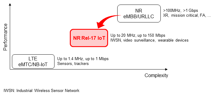
Figure 1 Rel-17 IoT position
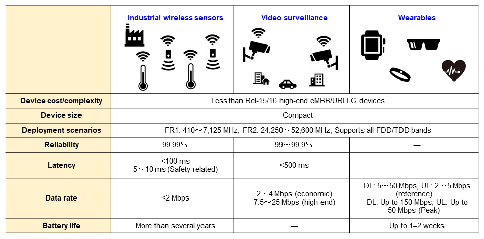
Figure 2 Rel-17 IoT use cases and requirements
2.3 New Coverage for Aerial, Marine and Mountainous Areas
To implement a range of industry-collaboration solutions, it is desirable to expand 5G networks over areas not previously covered by mobile networks, such as in the air, at sea, and in mountainous areas. However, this would be very difficult using conventional terrestrial base stations in terms of cost, and resilience in the event of disaster would also be an issue. As such, Non-Terrestrial Networks (NTN)*9 have been attracting attention for expanding the coverage of 5G networks (Figure 3), and discussion is progressing at 3GPP with participation from several enterprises in the satellite communications industry. Expanding 5G networks in this way will enable provision of mobile broadband communications, broadcasting, public safety and other services at all times, including while moving and during disasters. Some concrete use cases for NTN are summarized in reference [3], and can be categorized into four types, as shown in Figure 4.
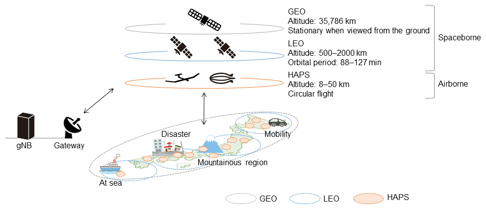
Figure 3 NTN overview
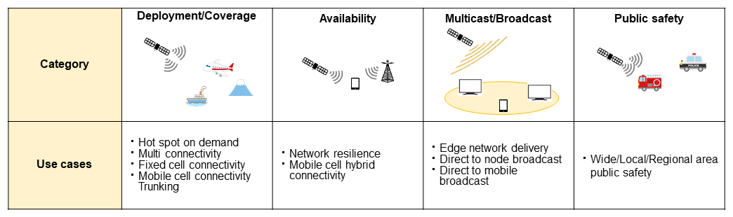
Figure 4 NR NTN use cases
- Factory motion control automation: Refers to automation control systems that precisely control periodic prescribed motions (moving or rotating) for production equipment in a factory. For example, it would be built into the motion automation control systems of a large printing or packaging machine.
- Deterministic communications: Communications that guarantee arrival of the data within a permitted delay period.
- GNSS: Generic name for satellite positioning systems such as GPS and Quasi-Zenith Satellite System (QZSS).
- RAT: Radio access technologies such as NR, LTE, 3G, GSM, and Wi-Fi.
- AGV: A type of driverless transport or mobile robot able to automatically transport products or materials in a factory or warehouse.
- NB-IoT: An LTE communications specification for low data rate communications for IoT devices (sensors, etc.) using a narrower bandwidth than eMTC.
- eMTC: An LTE communications specification for low data rate communications for IoT devices (sensors, etc.) using a narrow bandwidth.
- NTN: Any network in which the communications area is not limited to the ground but extended to other places such as the air, sea, and space through the use of non-terrestrial equipment such as satellites and HAPS (see *125).
-
Rel-17 incorporates study and specification ...
Open
Rel-17 incorporates study and specification of radio technologies for implementing the three industry-collaborations described above and various others as well. For example, URLLC, Time Sensitive Networks (TSN)*10, positioning*11, and RAN slicing are promising for smart factory applications, Reduced Capability (RedCap), as described below is promising for IoT, and NTN is promising for new coverage in the air, at sea, in the mountains and other areas.
3.1 URLLC
1) Technical Enhancements for Low-latency Communication
(a) Physical Uplink Control CHannel (PUCCH)*12 transmission and retransmission with sub-slot configuration*13
For URLLC, the PUCCH transmission function with sub-slot configuration was enhanced. In Rel-16, only single transmission of the Hybrid Automatic Repeat reQuest-ACKnowledgement (HARQ-ACK)*14 was supported with sub-slot configuration PUCCH. In Rel-17, as shown in Figure 5, sub-slot retransmission of PUCCH is also supported. In addition to HARQ-ACK, sub-slot PUCCH transmission is supported for all other Uplink Control Information (UCI)*15 including Channel State Information (CSI)*16, and Scheduling Requests (SR)*17.
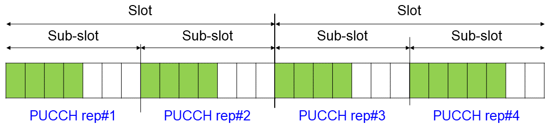
Figure 5 PUCCH repeated transmission based on sub-slot configuration
(b) PUCCH cell switching
User Equipment (UE) up to Rel-16 can transmit PUCCH only on a Primary Cell (PCell)*18, Primary Secondary Cell (PSCell)*19, or PUCCH-SCell*20 with radio resources*21 configured for PUCCH transmission. However, with Time Division Duplex (TDD)*22 operation, if there are not many chances to transmit on the UpLink (UL) due to the TDD configuration on any of the above cells that can transmit PUCCH, PUCCH transmission delays could occur. For this reason, a function was specified that can transmit the PUCCH of a cell on another cell with a different TDD configuration.
The destination PUCCH cell is configured according to the cell pattern with dynamic indication of Downlink Control Information (DCI)*23 or higher layer signaling*24. DCI dynamic indication indicates the destination PUCCH cell and slot for transmitting PUCCH. With higher layer signaling notifications, the cell pattern for each slot is configured, including the cell index indicating the destination PUCCH cell, the UE then determines destination PUCCH cell based on the cell pattern.
2) Technical Enhancements to Improve System Utilization Efficiency
(a) Delayed HARQ-ACK transmission occasion on a Semi-Persistent Scheduling (SPS)*25 Physical Downlink Shared CHannel (PDSCH)*26
A function was specified to delay HARQ-ACK transmission occasion on a SPS PDSCH. SPS PDSCH is transmitted from the gNodeB (gNB)*27 based on a schedule set by a higher layer. The gNB indicates the timing for the UE to send HARQ-ACK for the SPS PDSCH in the activation DCI, or it is configured using higher layer signaling.
If the timing of transmitting HARQ-ACK for the SPS PDSCH collides with the timing for a DownLink (DL) symbol, a Synchronization Signals/Physical Broadcast CHannel Block (SSB) symbol*28, or a COntrol REsource SET (CORESET) #0 symbol*29, transmission of the HARQ-ACK is suspended. As a result, the SPS PDSCH corresponding to the HARQ-ACK will be retransmitted, which can reduce system utilization, so a function was specified to delay transmission of the HARQ-ACK till the next UL slot when a collision as described above occurs (Figure 6).
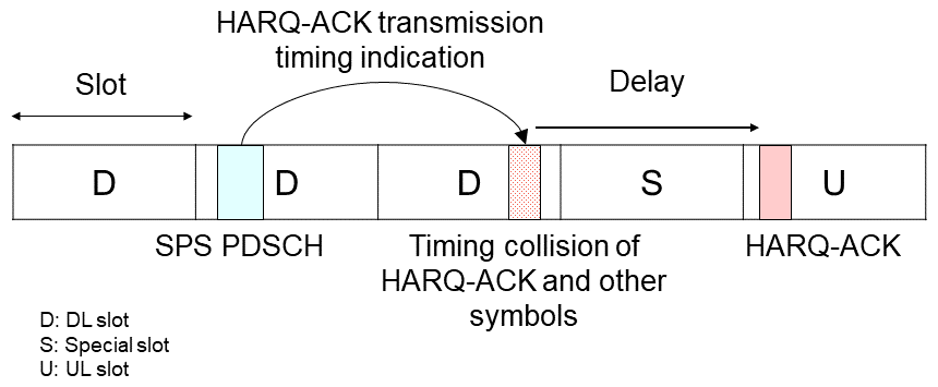
Figure 6 HARQ-ACK delayed transmission for SPS PDSCH
(b) Single HARQ-ACK retransmission
To improve system utilization efficiency, a method was specified for retransmitting a HARQ-ACK that was suspended due to collision with a DL symbol or a higher-priority HARQ-ACK. Specifically, the gNB dynamically transmits indication by DCI of the single HARQ-ACK CodeBook (CB)*30 for retransmission, and the UE retransmits the HARQ-ACK CB on the PUCCH slot indicated in the DCI indication.
(c) Type 3 HARQ-ACK CB function enhancements
Type 3 HARQ-ACK CB was specified in Rel-16, and in Rel-17, a function was specified to enable flexible changing of the number of HARQ-ACK bits*31 included. Type 3 HARQ-ACK CB included HARQ-ACK bits for all HARQ process numbers*32 of all Component Carriers (CC)*33. As such, there were many UCI bits, which could lead to lower system utilization. To resolve this, an Enhanced Type 3 HARQ-ACK CB was specified, which retransmits a HARQ-ACK CB that only includes the HARQ-ACK bits for any set of CCs or HARQ process numbers. The set of CCs or HARQ process numbers included in the HARQ-ACK CB is configured using higher layer signaling.
3) Technical Enhancements to Improve Transmission Reliability
(a) Type 1 HARQ-ACK CB*34 for HARQ-ACK transmission with sub-slot configuration
Rel-16 supported transmission of Type 1 HARQ-ACK CB, which semi-statically generates the HARQ-ACK CB, when sending HARQ-ACK for slot configured PUCCH. Also, for sending the sub-slot configuration PUCCH HARQ-ACK described above, it only supported Type 2 HARQ-ACK CB*35, which dynamically generates the HARQ-AC CB.
In Rel-17, Type 1 HARQ-ACK CB, which semi-statically generates the HARQ-ACK CB, is also supported for sending the sub-slot configuration PUCCH HARQ-ACK. With Type 2 HARQ-ACK CB, if the UE does not receive the DCI correctly, gNB and UE could expect different HARQ-ACK CBs, which could decrease communications reliability. However, with Type 1 HARQ-ACK CB the HARQ-ACK CB is generated based on information semi-statically set by the gNB, so this issue will not occur. Thus, it increases the reliability of HARQ-ACK transmission with sub-slot configuration.
For the procedure to generate Type 1 HARQ-ACK CB for sending a sub-slot configuration PUCCH HARQ-ACK, some changes to parts of the procedure for generating a slot configuration Type 1 HARQ-ACK CB were specified. Slot configuration Type 1 HARQ-ACK CB is generated with the following procedure.
Step (1): For the UL slot that will send the HARQ-ACK, the UE determines which DL slot can include the PDSCH indicating that that UL slot will send the HARQ-ACK.
Step (2): For the above DL slot, determine candidate occasions for receiving PDSCH (PDSCH reception occasion candidates) based on the Time-Domain Resource Allocation (TDRA) table*36.
Step (3): Of the above DL slot PDSCH reception occasion candidates, if there is overlap in the TDD configuration UL and settings, or the indicated slot/symbol and the Orthogonal Frequency Division Multiplexing (OFDM) symbol*37 units, then remove that PDSCH reception occasion candidate.
Step (4): For the remaining PDSCH reception occasion candidates, form groups of PDSCH reception occasion candidates that overlap in OFDM symbol units.
Step (5): The UE generates the HARQ-ACK bits for each group.
For the Type 1 HARQ-ACK CB of a sub-slot configuration PUCCH HARQ-ACK, Step (2) of the above procedure changes. In particular, for the DL slots determined in Step (1), the UE decides the PDSCH reception occasion candidates based on the notification from the gNB of the HARQ-ACK transmission timing, when sub-slot configuration is applied.
An example of this operation is shown in Figure 7. Below, we assume that the sub-slot configuration PUCCH HARQ-ACK was sent in sub-slot #6 in Fig. 7.
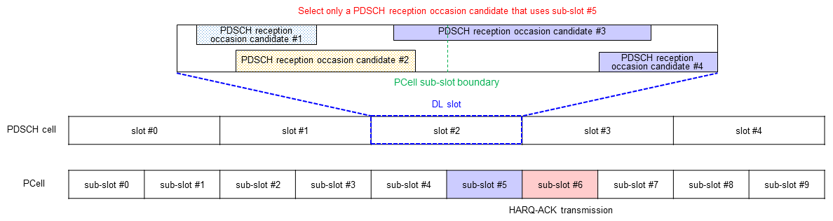
Figure 7 Procedure for generating Type 1 HARQ-ACK with sub-slot configuration
In Step (1), the slot that can contain the PDSCH that will be instructed to send the HARQ-ACK in slot #3 is determined to be DL slot #2. Here, it is assumed that the gNB sends notification that the HARQ-ACK will be sent one slot after the slot that contains the PDSCH, which could indicate that transmission of the HARQ-ACK corresponding to the PDSCH reception occasion candidate will be executed in slot #3. As such, it is decided that slot #2 will be the DL slot.
Next, the timing for sending the HARQ-ACK described in Step (2) is interpreted to be in sub-slot units, and the PDSCH reception occasion candidates for the above DL slot are determined. Here we assume the HARQ-ACK will be sent one sub-slot later, so we select a PDSCH reception occasion candidate in sub-slot #5, one sub-slot before sub-slot #6, which will send the HARQ-ACK. In the above DL slot, only PDSCH reception occasion candidates #3 and #4, which are at the same time as sub-slot #5 are determined to be PDSCH reception occasion candidates. Conversely, PDSCH reception occasion candidates #1 and #2 are not at the same time as sub-slot #5, so they are excluded from the candidates.
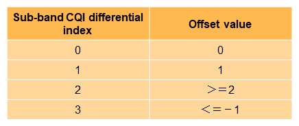
(b) Finer granularity sub-band*38 Channel Quality Indicator (CQI)*39 reports
Finer-granularity sub-band CQI reports have been specified. CQI reports can be performed in wideband*40 or sub-band units. In Rel-15 and Rel-16, sub-band CQI report values were reported, as shown in Table 1, using 2-bit offset values*41 (4 patterns) from the 4-bit values used as wideband CQI index values. If the offset value is greater than or equal to 2, or less than or equal to -1, the value reported is rounded to one of these values. Therefore, the sub-band CQI index could not be reported accurately, and a reduction in reliability could result, because the optimal Modulation and Coding Scheme (MCS)*42 could not be selected. Rel-17 specifies that the same 4-bit values (0-15) as are used for wideband are reported as actual values for sub-band CQI index.
Table 1 2-bit sub-band CQI report
4) Technical Enhancements for eMBB URLLC
For UL transmission from control equipment in a factory, when data and signaling from within a UE could have different latency and reliability requirements, a collision could occur within a UE, causing important control data to arrive late. To ensure that transmission of data with strict latency and reliability requirements is not interrupted, Rel-16 specified different priorities within UE and behaviors for when there is collision among multiple UL transmissions. Two levels of priority (high/low) are supported for the PUCCH, Physical Uplink Shared CHannel (PUSCH)*43 and Sounding Reference Signal (SRS)*44, and when there is a collision, the low-priority UL transmission is suspended and only the high-priority UL transmission is transmitted. Therefore, low-priority UL transmissions such as eMBB require retransmission, which could result in increased latency and decreased reliability. To improve latency and reliability of low-priority UL transmission, Rel-17 specifies a function to send both high-priority and low-priority UL transmissions for some combinations of collision. Two methods are specified as described below.
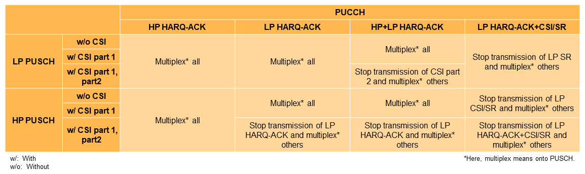
(a) Multiplexed transmission of low- and high-priority communications
When scheduling simultaneous transmission of low and high-priority transmissions in OFDM symbol units, low and high-priority UL transmissions are multiplexed on a single UL channel. However, only some combinations of collision support multiplexed transmission, and for other combinations, the low-priority UL transmission is suspended and only the high-priority UL transmission is executed. In particular, behavior is defined according to combinations of PUCCH UCI type and PUSCH collisions as shown in Table 2 and Table 3. For example, if a PUCCH containing only a low-priority HARQ-ACK and a PUCCH containing only a high-priority HARQ-ACK collide, the UE can multiplex both HARQ-ACKs and send them using high-priority PUCCH resources. If a PUCCH containing only a low-priority SR collides with a PUCCH containing only a high-priority HARQ-ACK, the UE will suspend transmission of the low-priority PUCCH and send only the PUCCH containing the high-priority HARQ-ACK. Note that for collision combinations not included in Table 2 and Table 3, the UE will suspend the low-priority UL transmission and execute only the high-priority UL transmission.
Table 2 PUCCH collision behavior
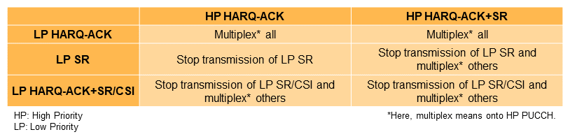
Table 3 PUCCH and PUSCH collision behavior
(b) Simultaneous transmission of low- and high-priority communications
For inter-band Carrier Aggregation (CA)*45, a function is specified that can send both channels simultaneously if there is a collision at the OFDM symbol level between PUCCH and PUSCH with different priorities in different cells. This function is intended to reduce delay and increase reliability of low-priority UL channels.
5) Technical Enhancements for URLLC Functions in Unlicensed Bands*46
Use of unlicensed bands for New Radio (NR) has been studied and NR Unlicensed (NR-U) was specified as a function of NR Rel-16. In Rel-17, the following functional enhancements were made to improve compatibility of URLLC functions with unlicensed bands and to further reduce latency.
(a) UE-initiated Channel Occupancy Time (COT)*47 in Frame Based Equipment (FBE)*48 behavior
In Rel-16 NR-U with FBE behavior [4], only gNB-initiated COT [4] is supported, and transmission is always initiated from the DL. In Rel-17, UE-initiated COT was added to reduce latency of UL transmission. If a UE has UL traffic, it performs periodic Listen Before Talk (LBT)*49[5], and if no other transmission is detected, it initiates COT and begins UL transmission in that COT.
(b) Optimization of NR-U introduced in Rel-16 and URLLC Configured Grant (CG) PUSCH*50 configuration
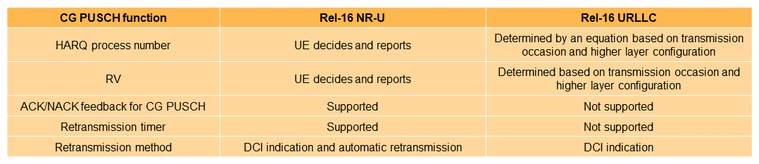
In Rel-16, separate functional enhancements on CG PUSCH for NR-U and URLLC were made. Rel-16 NR-U and URLLC CG PUSCH behavior are shown in Table 4. Different behavior for NR-U and URLLC was specified in Rel-16, for deciding HARQ process numbers and Redundancy Version (RV)*51, for transmitting HARQ-ACK for CG PUSCH, among others. No method for switching these behaviors was defined in Rel-16, so this was clarified for URLLC in Rel-17. Specifically, configuration by higher layer signaling is used to switch the applicable behavior.
Table 4 Rel-16 CG PUSCH behavior for NR-U/URLLC
3.2 TSN
1) Highly Precise Time Synchronization
There is strong demand for highly accurate time synchronization among production machines such as robots in a smart factory. Conventionally, production machines have been connected using Ethernet cables to a Grand Master Clock (GMC)*52 and synchronization is done based on a TSN protocol*53 (IEEE Std 1588*54, IEEE Std 802.1AS*55, etc.). However, wire cables have disadvantages such as being difficult to manage and inflexibility when making production-line changes. For this reason, Rel-16 introduced a highly accurate time synchronization mechanism using the 5G System (5GS)*56.
The Rel-16 specifications included a function to broadcast or unicast a precise reference clock (with 10 ns time granularity) from the base station to a UE in order to implement highly accurate time synchronization between UE and a gNB. However, if the cell diameter is large, error in the reference signal occurs between the time of transmission by the gNB and the time of reception by the UE due to radio propagation delay.
Therefore, Rel-17 defines a function for time synchronization which compensates for propagation delay between the UE and gNB. In particular, it specifies two types of compensation method, based on Timing Advance (TA)*57 and Round Trip Time (RTT)*58, respectively. For the former, the TA value is subtracted from the reference time to obtain the clock information with the effect of propagation delay. For the latter, the following procedure for measuring the propagation delay is performed, thereby compensating for propagation delay more accurately than using TA (Figure 8, 9).
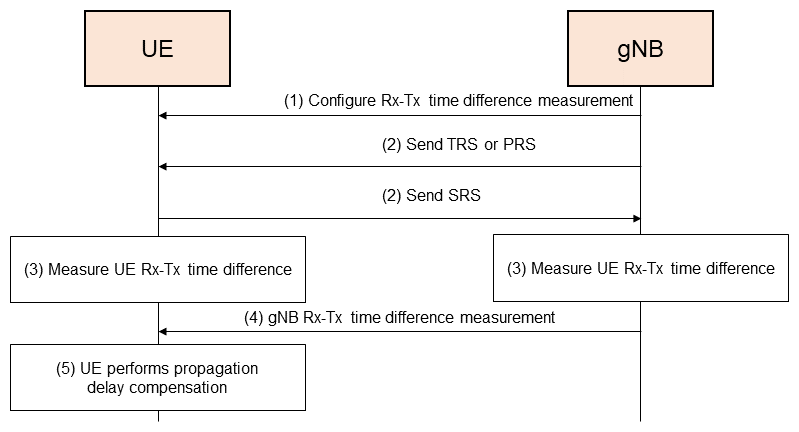
Figure 8 Procedure for measuring propagation delay based on RTT at UE
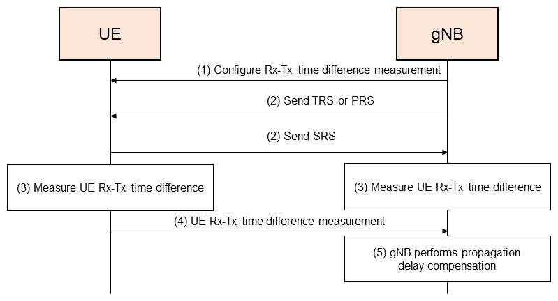
Figure 9 Procedure for measuring propagation delay based on RTT at gNB
- The gNB configures an Rx-Tx time difference*59 measurement on the UE.
- The gNB sends a Tracking Reference Signal (TRS)*60 or a DL Positioning Reference Signal (DL-PRS*61). The UE also sends an SRS to the gNB.
- Considering that there could be a difference in propagation delay between the UL and the DL, both the UE and gNB measure the Rx-Tx time difference between them.
- The gNB sends the measured Rx-Tx time difference from the gNB side to the UE.
- The UE computes the propagation delay based on the Rx-Tx time differences measured at the UE and gNB and compensates for it.
Compensation for propagation delay can be done on either the UE or the gNB. In Fig. 8, the UE is performing the compensation, but as shown in Fig. 9(4), a method is also specified for the UE to send the result of measuring the UE Rx-Tx time difference to the gNB and the gNB can compensate for propagation delay.
2) Technology to Improve Reliability Based on TSN Traffic
Rel-16 specified notifications sent from the Access and Mobility management Function (AMF)*62 to the gNB with assistance information such as Time Sensitive Communication (TSC)*63 traffic patterns. Using this assistance information, the gNB can plan more-efficient, deterministic data scheduling by selecting CG, SPS and dynamic grant*64 according to TSC traffic characteristics.
TSC assistance information introduced in Rel-16 included periodicity*65 and burst arrival time*66, and Rel-17 added new information called survival time*67. Based on this information, the base station scheduler can understand the urgency of TSC traffic scheduling, schedule appropriately, and configure reliable radio links.
Enhancements were also made to increase UL data transmission reliability. In particular, when radio quality is poor, the UE can transition to a state called survival time state, through CG retransmission scheduling by the gNB. In the survival time state, the UE can autonomously activate multiple internal Radio Link Control (RLC) entities*68 to increase redundancy with duplicate data transmissions and prevent data transmission failure. In such cases, the RLC entities used for data duplication are pre-configured from the base station for each Data Radio Bearer (DRB)*69.
3.3 Positioning
NR Positioning, which is a positioning function that uses the RAT signal, was adopted in Rel-16. As mentioned above, Rel-17 specifies technology for implementing accurate and low-latency positioning that can meet strict requirements in smart factories. Anticipating a wide range of other use cases, other functional enhancements were also made to increase accuracy and reduce latency of positioning. Technology was also specified for evaluating the reliability of positioning when using GNSS signals.
1) Technology to Improve Positioning Accuracy
RAT-based positioning with NR uses a reference signal dedicated for positioning, referred to as a PRS. Positioning methods using a PRS can be categorized into timing-based methods, including DL Time Difference Of Arrival (DL-TDOA)*70, UL-TDOA*71, and Multi-RTT*72; and angle-based methods, including DL Angle of Departure (DL-AoD)*73 and UL Angle of Arrival (UL-AoA)*74. For each of these, the Transmission and Reception Points (TRP)*75 and data measured by the UE are different. Rel-17 specifies functions to improve positioning accuracy for both (a) timing-based and (b) angle-based methods.
(a) Timing-based
Timing-based methods estimate position from the difference in PRS arrival times or the round-trip arrival times between a TRP and the UE using PRS transmission and reception times for this calculation.
The PRS is generated and processed as a baseband*76 digital signal, converted to an analogue signal, and transmitted from the antenna, but in Rel-16, the times used as the PRS transmission and reception times were when the signals are still in digital form. As such, the latency of conversion to an analogue signal was not considered, resulting in ns-order time errors that degraded positioning accuracy.
Rel-17 targets positioning accuracy of sub-meter order, so it adopts functions to compensate for this ns-order time error. In particular, it specifies a grouping called Timing Error Group (TEG) with time error that is the same, and uses a mechanism for calculating the time error for TEGs with relatively large time error. For example, if multiple TEGs composed of antenna panels or antenna elements receive the same PRS, different measurements (e.g., Reference Signal Received Power (RSRP)*77, UE/gNB Rx-Tx time difference, Reference Signal Time Difference (RSTD)*78, or Relative Time Of Arrival (RTOA)*79) can be reported to the Location Manager Function (LMF)*80, and this can be used to estimate time error and mitigate its effects. It will depend on the implementation, but TEGs are expected to be groups of antenna panels or antenna elements.
(b) Angle-based
Angle-based methods estimate position from the arrival angle or departure angle of the PRS.
Rel-16 included specifications for positioning using the angle of arrival or departure of the PRS resource with the largest reception power. However, in environments where there are direct, Line-Of-Sight (LOS)*81 signals between a TRP and the UE but there are PRS resources that have stronger reception power even though they are reflected, more accurate results can be expected from using the direct signal rather than the reflected signal, even though it is stronger.
As such, Rel-17 uses a function that computes position using the PRS resource that is detected earliest in time. It also adds a function that evaluates the probability that the propagation path is LOS as a binary value of 0 or 1, or as a value from 0 to 1 in increments of 0.1. To improve propagation environment modeling using recent advances in Machine Learning (ML)*82 technology, the number of propagation paths that can be reported from gNB or UE to the LMF was also increased from two to eight. To also optimize the PRS departure and arrival directions at gNB and UE, a function to notify gNB and UE of the assumed PRS resource departure or arrival angle was also added.
2) Technology for Low-latency Positioning
To achieve low-latency positioning requirements for smart factories with Rel-17 positioning, four types of functional enhancements were added: (a) pre-set Measurement Gap (MG)*83 based positioning, (b) MG-less positioning, (c) Radio Resource Control Inactive state (RRC_INACTIVE)*84 positioning, and (d) on-demand DL-PRS.
(a) Pre-set MG based positioning
For the Rel-16 positioning function, when a UE measures the DL-PRS on a non-serving frequency*85, the MG must be configured. However, setting the MG requires RRC*86 signaling from the gNB, which can increase latency.
As such, Rel-17 extended functionality to pre-set the MG. Pre-setting of the MG is done using RRC signaling, and when it is needed, it is activated using a Medium Access Control Control Element (MAC CE)*87 from the gNB. Pre-setting the MG reduces configuration latency relative to using RRC signaling. Details of the configuration procedure are given below (Figure 10).
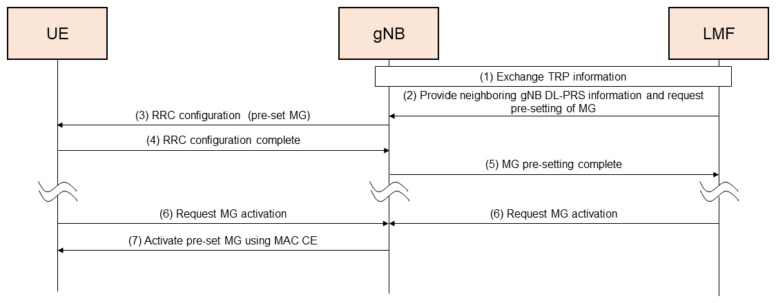
Figure 10 Procedure for pre-set MG based positioning
- As a preparatory step, the LMF exchanges TRP data needed for positioning with the serving and neighboring gNBs.
- The LMF provides DL-PRS information from neighboring gNB to the serving gNB*88 and requests pre-setting of the MG.
- Using RRC signaling, the serving gNB pre-sets the MG on the UE based on supplementary data from the LMF and the UE capabilities.
- The UE sets the MG and returns a completion RRC message to the serving gNB.
- The serving gNB returns the setting-completed message to the LMF.
- When the MG is needed, the UE or LMF sends a request to activate the MG to the serving gNB.
- The serving gNB sends a MAC CE to the UE, indicating activation of the MG.
If, for example, a positioning request is made to the UE before the MG is activated, the UE will request the gNB for a MG update using a UL MAC CE, and the gNB will activate a different MG using DL MAC CE. Also, in Rel-16, four DL-PRS measurement samples*89 were used by the UE when making DL-PRS measurements to take the average of measured data (such as RSRP), but to reduce latency, new options for one or two measurements were added, so that the functions can be configured flexibly for one, two, or four samples, according to purpose.
(b) MG-less positioning
In addition to reducing the latency of pre-set MG-based positioning, Rel-17 specifies a MG-less positioning function that enables the UE to measure DL-PRS outside of a MG, for cases when positioning with flexibility and low latency are a higher priority. In particular, these specifications include a PRS Processing Window (PPW), when DL-PRS can be received outside of the MG, and reception priorities between DL-PRS and other DL signals when setting PPW timing. If a DL-PRS has been configured in the PPW and there is no collision with other high-priority signals, the UE can measure the DL-PRS without using a MG.
At most four PPWs can be set in each DL BandWidth Part (BWP)*90, and for positioning requests from an LMF to gNB, at most one PPW per active DL BWP and no more than four PPWs for all active DL BWP can be activated. UE behavior if there is a collision between a DL-PRS and another DL signal (Physical Downlink Control CHannel (PDCCH)*91, PDSCH, Channel State Information-Reference Signal (CSI-RS)*92), was also discussed, and a priority state was specified, notifying the UE beforehand of the reception priority for DL-PRS and other DL signals. To increase flexibility of DL-PRS measurements with respect to UE capabilities, the granularity of reception priorities was also specified in units of DL CC or active DL CCs, for each PPW and symbol level. For example, if the same priority state is applied to DL CCs and the UE is able to decide reception priority at the symbol level, DL-PRS and other DL signals can be received in different symbols of the same PPW, but a UE able to decide reception priority at the PPW level can only receive one of DL-PRS or another DL signal in the same PPW. However, these reception priorities do not apply to SSB, which are always received with the highest priority. Thus, even when DL signals such as PDCCH or PDSCH have been scheduled, if there is a high-priority positioning request from the LMF, the UE can prioritize receiving the DL-PRS and perform positioning.
(c) Positioning with RRC_INACTIVE state
Previously, positioning was performed after the UE moved from the RRC_IDLE*93 state to the RRC_CONNECTED*94 state, but this transition was a source of additional delay. For industrial IoT devices in particular, in most cases there were no following communications packets after a positioning operation and the device would return to the RRC_IDLE state. This transition from RRC_IDLE to RRC_CONNECTED each time positioning was done was inefficient and increased device power consumption.
Rel-17 introduced a new positioning method in the RRC_INACTIVE state. Specifically, in the RRC_INACTIVE state the UE uses the Rel-17 Small Data Transmission (SDT)*95 framework, and sends and receives positioning messages and SRS settings with the gNB using random access*96 or CG.
(d) On-demand DL-PRS
There are cases when a DL-PRS for positioning is sent from a gNB but not used for positioning, and reception by the UE results in unnecessary power consumption. On the other hand, setting the DL-PRS period to be longer to conserve power can result in additional positioning latency. To deal with this issue, on-demand DL-PRS was introduced, which is only sent when it is needed.
Transmission of on-demand DL-PRS can be requested by either UE or LMF. The following procedure is used by the UE to make a request (Figure 11).
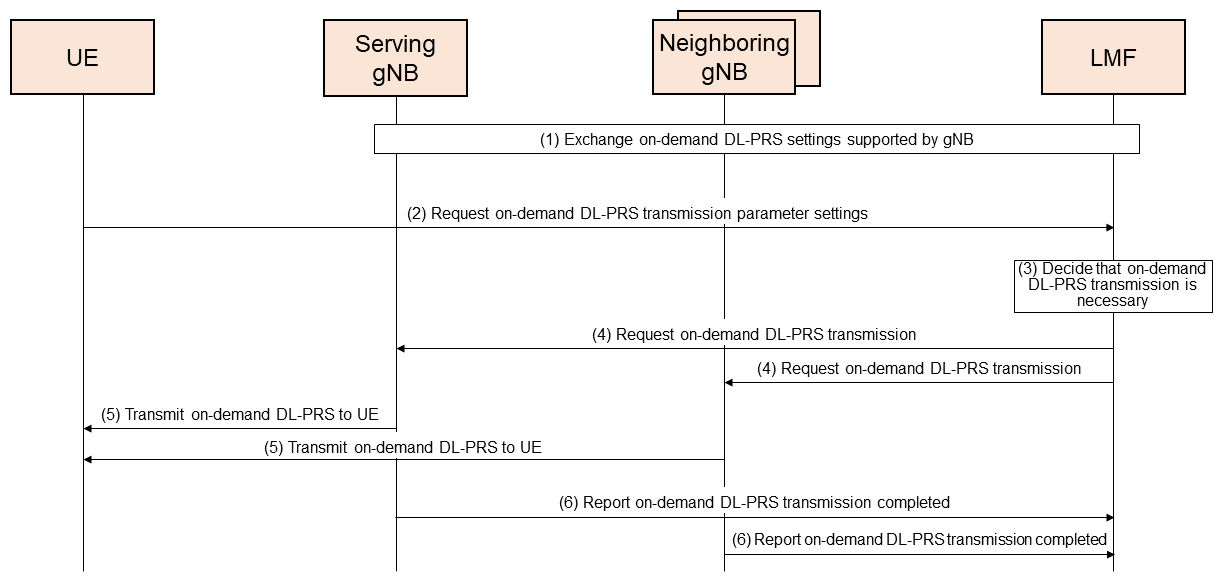
Figure 11 On-demand DL-PRS request procedure
- The LMF and gNB exchange on-demand DL-PRS settings that they support.
- The UE requests on-demand DL-PRS transmission parameter settings (DL-PRS start time, frequency, bandwidth, period, etc.) from the LMF.
- The LMF decides to send the on-demand DL-PRS.
- The UE needs to measure DL-PRS from the serving gNB and neighboring gNB, so the LMF requests them to also send on-demand DL-PRS.
- The serving gNB and neighboring gNB send on-demand DL-PRS to the UE.
- The serving gNB and neighboring gNB report to the LMF when on-demand DL-PRS transmission has completed.
Note that for (4), if a DL-PRS transmission is already in progress, the LMF can change the parameters of the DL-PRS in progress rather than sending an on-demand DL-PRS.
3) Integrity
Integrity of positioning refers to an index that gauges the reliability of the positioning information obtained. The index can be compared with the reliability required for the particular use case, and if that reliability cannot be ensured, any malfunction or accident caused by the positioning data can be avoided by issuing a timely warning to the user. Integrity can be used to implement safe operation of smart factories, as mentioned earlier, or other services requiring reliability (e.g., control in the fields of aviation, automobiles, railways, or distribution, financial service applications, etc.).
In Rel-17, integrity functions are provided for “GNSS-based positioning,” and mainly consist of “notification of information on each error source,” “unsuitable satellite notifications,” and “ensuring safety by use case.”
It is now possible to notify UEs through the network of sources of positioning error due to satellite conditions (orbit, clock, bias error, ionosphere signal delay, etc.). It is also possible to notify a UE that “a particular satellite cannot be used,” if information suitable for the integrity function to provide is not available from the satellite, such as when the clock error is larger than a threshold. Some of this information can be provided to a UE as system information*97, making available much necessary information to most UEs, even if they are using the integrity function.
Ensuring safety according to use case is done mainly by evaluation of three indices: Time To Alert (TTA)*98, Alert Limit (AL)*99 and Target Integrity Risk (TIR)*100. Considering sources of GNSS error, a Protection Level (PL)*101, which is an upper limit for positioning error, is derived for the desired TIR for the use case. If the PL is small for the AL, it indicates that the reliability is adequate, and the difference is a margin for ensuring safety. Conversely, if the PL is large relative to the AL, a warning can be issued within the TTA, so the user or application can be aware that the service cannot be used, or that a different measure will need to be used.
This function is provided in Rel-17 for GNSS-based positioning, but there are plans to extend it to RAT-based positioning in Rel-18.
3.4 RAN Slicing
Network slicing in 5G is a new function that is highly anticipated in industry. It enables a network to be partitioned into multiple logical networks to provide services according to various needs. This function has been standardized in the 5G Core network (5GC)*102, and in Rel-17, slicing functionality has been extended to the RAN.
1) Slice-aware Cell Reselection
Conventionally, cell reselection by a UE in the RRC_IDLE state has been done by considering the radio signal quality. However, when a UE needs to use a particular slice, there can be cases when a UE selects a cell with good quality and requests a connection, but then finds that the cell does not support the desired slice. In such a case, the UE first enters the RRC_CONNECTED state and then must move to another cell. This process of cell selection and connection is inefficient and increases latency, especially for UE using URLLC services. As such, Rel-17 introduces a cell selection function that is aware of slices and does not require entering the RRC_CONNECTED state.
Specifically, the network can now send the UE information supplementing cell reselection with awareness of slices in system information or RRC Release*103 messages. Examples of such supplemental information include cell reselection priorities by frequency and slice group and a list of cells supporting a slice group. Here, a slice group is a grouping of similar slices. For security reasons, mechanisms using slice groups do not directly report identifiers of slices they are accommodating, but rather apply a slice group identifier, which is reported. A UE sends notification from its Non-Access Stratum (NAS)*104 layer to its Access Stratum (AS)*105 layer, of the slice groups for the service it wants to use and their priorities. The AS layer performs cell reselection based on the slice group priorities and the slice-aware cell reselection supplemental information received from the network. This function enables the UE to accurately select a cell that provides the slice it needs to use.
2) Slice-aware Random Access CHannel (RACH)*106 Priority Control
To enter an RRC_CONNECTED state from the RRC_IDLE state, a UE must use random access. There are two types of random access: with and without collisions. For the former, the UE selects a channel from the RACH preamble*107 pool in the system information and transmits to the gNB. If another UE selects the same RACH preamble at the same time, a collision will occur. For the latter, random access is done using a RACH preamble specified by the gNB, so connection to the network proceeds smoothly, without collision.
In random access with collisions, if the UE does not complete a connection due to collision, it waits for a period of time called the random access backoff*108, and then re-attempts random access while increasing its transmit power (power ramping*109). This backoff period increases latency, so the procedure is not desirable for services requiring low latency.
For UE using high-priority slices, Rel-17 enables special parameters for power ramping and backoff to be set. Specifically for backoff, a UE using high-priority slices can now reduce the backoff period relative to an ordinary UE by multiplying by a scaling coefficient*110. For power ramping, the increase in transmit power can be set larger than an ordinary UE, making it easier to resolve priorities.
A new function called RACH resource partitioning was also introduced. This function partitions RACH resources and reserves some for users of high-priority slices so that they can use these dedicated RACH resources to avoid collisions with ordinary UE during random access. The gNB notifies a UE of slice groups with RACH priority control in the system information, and the UE refer to the notification of slice groups and their priorities from the NAS to the AS when deciding whether the RACH priority control parameters for high-priority slices or the dedicated RACH resources can be used.
3.5 RedCap
As mentioned earlier, Rel-17 provides specifications for mid-range IoT services, which fill in the space between the low-end IoT services that provide LTE-IoT (a type of Low Power Wide Area (LPWA)*111 service) including NB-IoT and eMTC, and high-end IoT services for URLLC and industrial IoT. Devices covered by these specifications are called Reduced Capability (RedCap) devices.
1) Reduced Capabilities and Cost Reduction
To reduce device costs while satisfying the requirements in Fig. 2, Rel-17 RedCap specifies the following reduced capabilities. The results of discussion at 3GPP regarding the reduced capabilities to reduce cost relative to non-RedCap devices (high-end IoT devices) are shown in Table 5 [6].
Table 5 Rel-17 Cost reduction of reduced capabilities for RedCap devices
- The maximum supported UE bandwidth: 20 MHz (Frequency Range 1 (FR1)*112) or 100 MHz (FR2*113).
- Number of receiver branches/Maximum DL Multi-Input-Multi-Output (MIMO)*114 layers: 1 or 2.
- Relaxed requirement for supported modulation order*115: Support for 256 Quadrature Amplitude Modulation (256QAM)*116 is optional (FR1 DL).
- Duplex mode*117: Half Duplex (HD)*118-Frequency Division Duplex (FDD)*119.
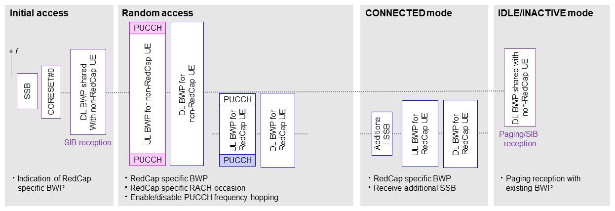
In specifying these reduced capabilities, it is assumed that RedCap and non-RedCap devices will operate in the same cells, so consideration was given to co-existence of both. In particular, specifications were set related to BWP so that common signals transmitted by gNB such as the SSB, System Information Blocks (SIB)*120, paging signals*121, and DL/UL signals related to random access are transmitted on the same or different frequencies for RedCap devices than non-RedCap devices, depending on the gNB configuration (Figure 12). In Fig. 12, a BWP for DL/UL signals related to random access has been configured for RedCap devices. Functions were also specified for devices to indicate that they are RedCap during their initial access, and for the gNB to indicate whether a RedCap device can access the cell.
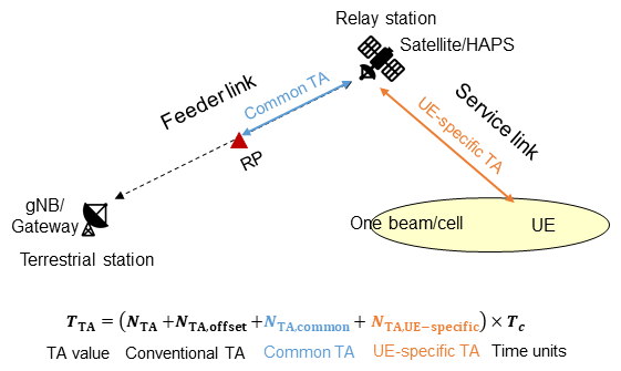
Figure 12 Example of RedCap device BWP operation
2) UE power saving Functions
To satisfy the battery life requirements in Fig. 2, Rel-17 specifies the following UE power saving functions. These functions have been specified for RedCap devices, but non-RedCap devices can also support them.
- Extended Discontinuous Reception (eDRX) while in standby (RRC_IDLE/INACTIVE states): Maximum DRX*122 periodicity of 10,485.76 s in RRC_IDLE state and 10.24 s in RRC_INACTIVE state.
- Relaxed neighboring cell Radio Resource Management (RRM)*123 measurement: RRM measurement periodicity of 1h or more (stationary devices and devices not at cell edge).
For example, studies by 3GPP reported that extending the DRX periodicity to 10,485.76 s reduced power consumption by up to 80 or 90%, and extending the RRM measurement periodicity to one hour reduced power consumption by up to 40% [6].
Rel-17 also specifies UE power saving functions for devices in the RRC_IDLE/INACTIVE and RRC_CONNECTED states [7], and although these apply to any device, they can also be applied to Rel-17 RedCap devices.
3) Coverage Enhancement Functions
As shown in Fig. 2, there is a requirement to make RedCap devices smaller, so a study was done at 3GPP regarding coverage if the antenna gain*124 for FR1 was reduced by up to 3 dB relative to non-RedCap devices. The study showed that RedCap device coverage for the following channels would degenerate as shown, using non-RedCap device coverage bottle-neck channels as the basis [6].
- PUSCH: 3 dB
- Msg2 PDSCH in random access: 1 to 6 dB
- Msg3 PUSCH in random access: 3dB
- Msg4 PDSCH in random access: 2 to 3 dB
- Cell common PDCCH: 1 dB
For the above channels, for PUSCH and Msg3, no particular specifications were made for Rel-17 RedCap devices, but Rel-17 specifies functions that enhance coverage for any type of device [7], and these can be applied to Rel-17 RedCap devices. For the other channels above, it was concluded that any degeneration of coverage could be resolved by the gNB implementation or using existing technologies, so there was no need to specify further technology for coverage enhancement.
3.6 NTN
The 3GPP specifications for NTN, as shown in Fig. 3, assume use of satellites such as GEostationary Orbit (GEO) and Low Earth Orbit (LEO) satellites, and aircraft such as High Altitude Platform Stations (HAPS)*125, which act as relay stations in the stratosphere. GEO, LEO and HAPS operate at altitudes of 35,786 km, 500-2,000 km and 8-50 km, and have transmission delays of approximately 120 ms, 3 ms, and 0.1 ms, respectively. The functionality needed to implement communications between devices and base stations in environments with these relatively large propagation delay have been discussed and specifications have been created. The specifications assume small devices, such as Very Small Aperture Terminal (VSAT) devices*126 and smartphones, and are assumed to provide GNSS functionality.
1) Time/Frequency Synchronization*127
As stated, propagation delays are very large, and relay stations could move, so a new synchronization function in the time-domain is needed. Relay stations move along a regular path, i.e., an orbit, so a method of determining a TA value was used for the time-domain synchronization function. Specifically, in addition to the conventional method for determining a TA value, methods of computing TA values for propagation on the feeder link*128 (common TA) and on the service link*129 (UE-specific TA) were introduced, and the sum of these is used as the final TA value. An overview is shown in Figure 13. Note that common TA is not the TA value for all segments of the feeder link, but rather for the segment between the relay station and a Reference Point (RP). The RP can be any point between the ground station and the relay station, and is decided by the network. If the ground station is used as the RP, DL/UL timing is aligned at the ground station so that the complexity of the network implementation is avoided, and if the relay station is used as the RP, the common TA will always be 0, so UE operation is simplified.
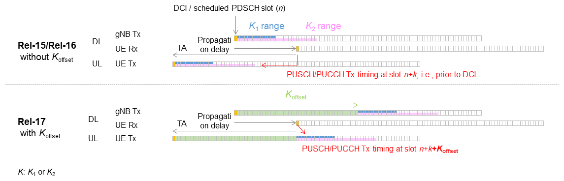
Figure 13 Determining TA value for NTN
The formula for computing common TA is defined (as a Taylor series*130 to the 2nd order), and the coefficients of each parameter in the formula are given as parameters. Notification of these parameters is given in a SIB defined for NTN. UEs retrieve them before transmitting on the Physical Random Access CHannel (PRACH)*131, and also periodically receive the same SIB after RRC connection establishment, to update the derivation equation. The frequency of receiving this SIB is dependent on the network, and the SIB also gives notification of how long the coefficients will be valid. The feeder link is common among UEs, and this part cannot be seen by each UE, so the adopted method is that common TA is calculated based on relative parameters broadcasted from the network.
The UE-specific TA is computed based on the UE's position and the relay station orbit information. The computation method is not specified, and is dependent on UE implementation. Position is obtained by GNSS, and the relay orbit information is obtained and updated in the same way as the common TA computation coefficients.
In addition to time synchronization, frequency synchronization operation is also performed. Movement of the relay station results in frequency shift*132, so each UE pre-compensates UL transmissions using position and orbit information similarly to how UE-specific TA is computed, as described above. Note that a specific compensation method is not specified and will be implementation dependent. Frequency shift compensation on the feeder link is performed at the ground station, so no operation at each UE is specified.
2) Scheduling/HARQ
The TA value determined using the method described above can be very large, so the difference in timing between the DL reception time in a given slot n, and the UL transmission time after applying the TA can be very large. In such cases, the offsets between slot n for receiving the DL signal and the slot for transmitting the UL signal corresponding to that DL signal (offset K1 between PDSCH and PUCCH, and K2 between PDCCH and PUSCH) must be very large. However, as shown in Figure 14, with the offsets that could be applied in specifications up to Rel-16, only a slot that is earlier than slot n can be indicated for the transmission. To resolve this issue, Rel-17 NR NTN introduces a Koffset parameter. The UL transmission slot is decided using a value of Koffset added to K1 or K2 for the above offset. This enables indication of a transmission slot that is after slot n. Notification of the Koffset parameter can be sent in the NTN-specific SIB, as a UE-common parameter, but it can also be set independently for each UE.

Figure 14 NTN scheduling (case with the same subcarrier interval)
HARQ related functions have also been added. In the NR specifications, for a given HARQ process, between a PDSCH reception and a PUCCH transmission, the HARQ process is not able to be used for a different PDSCH. As such, in environments with large propagation delay, this results in a limit to the number of data packets that can be sent to a UE in succession. This issue can be resolved by either increasing the maximum number of HARQ processes from 16 to 32, or by disabling the HARQ feedback*133 function. Disabling the HARQ feedback function is configured for each HARQ process, so the HARQ feedback function can be maintained for transmission of important information.
3) Mobility
(a) Addition of distance between UE and cell reference position and cell coverage availability time to the triggers for cell reselection and HO
For NTN, due to the distance between a satellite and relay stations, the difference in signal quality between the serving cell and adjacent cells is smaller than with ordinary terrestrial networks. Considering this characteristic, in addition to the signal quality threshold used conventionally, the distance between the UE and the cell reference position*134 have been introduced as auxiliary triggers for cell reselection and HandOver (HO)*135.
Note that for quasi-earth-fixed cells*136 such as for HAPS, the NTN cell moves relative to the earth's surface, so cell reselection must be done considering the cell-coverage availability time till the UE leaves the cell. As such, in Rel-17 the cell-coverage availability time was introduced to the triggers for cell reselection and HO.
(b) Fixed threshold for distance between UE and cell reference position, t-service notification
Conventionally, for cell reselection from the RRC_IDLE state, the UE performs cell reselection when the signal quality from the serving cell drops below a set threshold. In contrast, with NTN a UE receives notification by SIB of a new threshold for the distance between the UE and cell reference position, so the UE can perform cell reselection when its distance to the cell reference position exceeds this threshold (i.e., the UE becomes geographically distant from the serving cell), even if the serving cell signal quality is greater than the threshold.
For quasi-earth-fixed cells, notification of a new parameter indicating when cell coverage will end (t-service) is also sent. The UE measures frequency for cell reselection before the t-service time arrives, and then performs cell reselection before the end of cell coverage.
(c) Addition of conditional events D1, A4, and T1
To increase the reliability of HO, Conditional Handover (CHO)*137, which was specified in Rel-16, can now also be applied to NTN. Rel-17 has also extended CHO related events to cover NTN characteristics.
For CHO execution conditions, in addition to previous conditional events A3*138 and events A5*139 based on signal quality, conditional event D1 has been added, which considers the distance between UE and cell reference position. Specifically, when the distance between the UE and the serving cell reference position exceeds the set threshold and the distance to an adjacent cell reference position is less than its (separately set) threshold, the conditions for this event are satisfied and CHO is performed.
Also, since for NTN, the difference in quality between the serving cell and the neighboring cell is small, in addition to the conditional events A3 and A5 for monitoring the quality of both the serving cell and the neighboring cell, the conditional event A4 was added, which only monitors the quality in the neighboring cell. Thus, if the quality in the neighboring cell exceeds a specified threshold, the event conditions are satisfied, and CHO is performed.
For quasi-earth-fixed cells, the cell coverage availability time must also be considered, so a new conditional event, T1, was also created to constrain the UE HO time period. After a prescribed time has passed and within a prescribed time period, the event condition is satisfied and CHO is performed. Before the prescribed time, or after the time period has passed, this event condition is not satisfied. This enables the HO timing to be controlled according to the cell coverage availability time.
Note that conditional events D1 and T1 must be configured simultaneously with one of the radio-quality-based conditional events, A3, A4, or A5, to enable HO to a cell with good radio quality at the right time, while considering the physical distance to the cell and the coverage availability time.
- TSN: A network that handles time strictly.
- Positioning: The process of determining position or location.
- PUCCH: Physical channel used for sending and receiving control signals in the uplink.
- Sub-slot configuration: Slots are partitioned into units of multiple OFDM symbols (see *36) for scheduling.
- HARQ-ACK: A reception confirmation signal that indicates the transmitting node whether the receiving node received (decoded) the data correctly.
- UCI: A general term for UL signals such as HARQ-ACK, CSI, and SR.
- CSI: Information describing the state of the radio channel traversed by the received signal.
- SR: A signal requesting UL radio resources to be allocated on a base station for the user device.
- PCell: Among the multiple carriers used for CA, the component carrier (see *32)/cell that maintains the connection.
- PSCell: The component carrier (see *32)/cell that maintains the connection among those carriers/cells supported by the secondary base station during DC or MR-DC.
- PUCCH-SCell: Among the multiple carriers used for CA, the component carrier (see *32)/cell that is not a PCell or PSCell, and has radio resources configured for sending PUCCH.
- Radio resource: Unit of time or frequency range allocated to each user for communications purposes.
- TDD: A signal transmission method in which the same carrier frequency or frequency band is partitioned into time slots used for UL and DL.
- DCI: Control information sent on the DL, including scheduling information needed for users to demodulate data, data modulation, channel coding rates, etc.
- Higher layer signaling: In this article, indicates signaling for device control in a higher layer such as the MAC layer or higher (e.g., RRC (see *86), messages, MAC CE (see *87), etc.).
- SPS: A scheduling technique for performing semi-persistent resource allocation.
- PDSCH: The physical channel used to transmit data packets on the DL.
- gNB: A radio base station for NR radio access.
- SSB symbol: Synchronization signal for detecting cell frequencies and timing required for communications and broadcast channel notifying of main radio parameters. Sent periodically by base stations.
- CORESET#0 symbol: The symbol for receiving control information, including scheduling information needed to receive SIB 1 (see *120) at initial access.
- HARQ-ACK CB: Indicates the applicable set of bits when multiple HARQ-ACK bits (see *30) are transmitted on a single UL channel.
- HARQ-ACK bits: Indicate ACK or Negative ACK (NACK) for HARQ, with 1 or 0 bits.
- HARQ process number: A process number for managing HARQ-ACKs for PDSCH reception.
- CC: A term used to refer to the carriers bundled together when using CA.
- Type 1 HARQ-ACK CB: A method that generates HARQ-ACK bits semi-statically and configures the HARQ-ACK CB, for PDSCH reception occasion candidates.
- Type 2 HARQ-ACK CB: A method that generates HARQ-ACK bits dynamically and configures the HARQ-ACK CB, for a PDSCH actually received.
- TDRA table: Candidate information for data channel time resource allocation for a device.
- OFDM symbol: A unit of data transmission, composed of multiple subcarriers in the case of OFDM. A Cyclic Prefix (CP) is inserted at the beginning of each symbol.
- Sub-band: One of the bands that result from splitting an entire frequency band into multiple parts.
- CQI: An index of reception quality measured at the mobile station, expressing propagation conditions on the DL.
- Wideband: Refers to the band of all frequencies.
- Offset value: An offset is a value indicating whether and how much a value deviates from a reference point.
- MCS: Combinations of modulation scheme and coding rate decided on beforehand when performing Adaptive Modulation and Coding (AMC).
- PUSCH: A physical channel used to transmit data packets on the UL.
- SRS: A reference signal used to measure UL channel quality, reception timing, etc. at the base station.
- Inter-band CA: CA using carriers in different bands.
- Unlicensed band: A frequency band that does not require government licensing, and whose use is not limited to a particular telecommunications operator.
- COT: A time period that a base station or device will occupy for data transmission.
- FBE: Behavior that performs LBT (see *48) based on carrier sense with fixed frequency and interval.
- LBT: A mechanism that enables a device to check whether another device is transmitting data before transmitting by radio.
- CG PUSCH: A mechanism by which a PUSCH resource pre-allocated to an individual user by a base station, so that if there is UL data, the device can send the PUSCH using that resource without a SR transmission.
- RV: In the data bit sequence after coding, the data bit sequence after decimation with a fixed period.
- GMC: A master clock used for highly accurate time synchronization, which distributes accurate time data to subordinate equipment.
- TSN protocol: Layer-2 protocols used for implementing real-time operation over Ethernet. TSN protocol specifications are created by the IEEE 802.1 Time-Sensitive Networking task group, and representative TSN specifications include IEEE Std 1588 and IEEE Std 802.1AS.
- IEEE Std 1588: An IEEE standard specification defining a highly accurate time synchronization protocol used in applications such as finance and communications systems.
- IEEE Std 802.1AS: A specification for time synchronization control used on local and metropolitan area networks.
- 5GS: The network system in 5GC, comprised of communication devices (UE) and the radio access network to which they connect.
- TA: Refers to the difference between the desired time for a UL signal from the base station to be received by the UE, and the actual time the signal is received.
- RTT: The delay required for a round-trip transmission between a device and the base station.
- Rx-Tx time difference: The difference between transmission and reception time for a signal.
- TRS: A reference signal used for tracking changes in the time or frequency on the DL.
- PRS: A reference signal specifically for positioning. For positioning, the DL-PRS is specified on the DL signal, and the SRS is specified on the UL signal.
- AMF: A logical node that accommodates base stations (gNB) and provides mobility control and other services.
- TSC: Communications for which real-time response is important.
- Dynamic grant: A mechanism by which a UE requests scheduling and the base station sends DCI for allocating UL data transmission resources.
- Periodicity: Refers to the cyclic nature of TSC traffic.
- Burst arrival time: The arrival time of the first packet of a data burst (data produced for a short period of time).
- Survival time: The time period over which an application can survive even without a data burst.
- RLC entity: A function that controls retransmissions on a sublayer of Layer 2.
- DRB: A bearer on a radio link where U-plane data flows.
- DL-TDOA: A positioning method in which the UE receives DL-PRS transmitted by multiple TRPs (see *75) and estimates position from the difference in arrival times.
- UL-TDOA: A positioning method in which multiple TRPs (see *75) receive UL-PRS transmitted by the UE, which are used to estimate position from the difference in arrival times.
- Multi-RTT: A positioning method in which multiple TRPs (see *75) send DL-PRS to the UE, the UE sends UL-PRS to multiple TRPs, and the difference in round-trip arrival times between the TRP and UE are used to estimate position.
- DL-AoD: A positioning method in which DL-PRS is sent from a TRP (see *75) to a UE and position is estimated from the departure angle of the TRP DL-PRS.
- UL-AoA: A positioning method in which UL-PRS is sent from a UE to a TRP (see *75) and position is estimated from the arrival angle of the TRP UL-PRS.
- TRP: The point of transmission and reception of radio signals at a base station.
- Baseband: The circuits or functional blocks that perform digital signal processing.
- RSRP: Received power of a signal measured at a receiver. RSRP is used as an indicator of receiver sensitivity in a terminal.
- RSTD: The relative difference in reception time between two Transmission Points (TP) mainly measured at UE.
- RTOA: The relative difference in reception time between two reception points (RP) mainly measured at TRP.
- LMF: A function specified in 5GC that provides communications and control for location services.
- LOS: Describes an environment where there are no obstacles between the transmitter and receiver, allowing them to communicate via direct waves.
- ML: A technology enabling computers to acquire knowledge, judgment criteria, behaviors, and other skills from data, similar to how humans gain such skills from perception and experience.
- MG: A frequency interval established to measure frequencies outside of frequencies used for communications.
- RRC_INACTIVE: An RRC (see *86) state in a UE, where the terminal does not have cell level identification within the base station, and where the context of the terminal is held in the base station and the core network.
- Non-serving frequency: A frequency that is not used as a serving frequency for transmission between a device and base station.
- RRC: A protocol for controlling radio resources in a radio network.
- MAC CE: A control signal with particular configuration transmitted on the MAC sub-layer.
- Serving gNB: The gNB that is connected with a device.
- Measurement sample: Here, this refers to a unit of DL-PRS resources used for measurement on a UE.
- BWP: A general term for a bandwidth, frequency location, or subcarrier interval, set in each CC, and used by the device for communications.
- PDCCH: Control channel for the physical layer in the DL.
- CSI-RS: A DL reference signal used by mobile terminals to measure the state of the radio channel.
- RRC_IDLE: A UE RRC state in which the UE has no cell-level identity within the base station and the base station stores no UE context. The core network stores UE context.
- RRC_CONNECTED: A state in which resources have been allocated between a UE and base station.
- SDT: A new function introduced in Rel-17 for IoT devices, enabling them to send small amounts of packet data while the UE is in RRC_INACTIVE state, using random access or CG resources.
- Random access: A method for initial access that a UE uses to establish UL synchronization with the base station, and to receive UL transmission resources from the base station.
- System information: Information broadcast in each cell, including location registration area numbers needed by mobile devices to determine whether location registration is necessary, neighboring cell information and radio quality information needed to enter those cells, and information regulating and controlling transmissions.
- TTA: The maximum elapsed time permitted for the integrity function to issue a warning when the PL (see *101) exceeds the AL (see *99).
- AL: The maximum error permissible by an application.
- TIR: The probability that the integrity function will not be able to report that AL is exceeded within the TTA. Expressed in units of probability per unit time.
- PL: An upper limit on the positioning error that can satisfy a TIR at a given time.
- 5GC: The core network specified by 3GPP for fifth-generation mobile telecommunications systems.
- RRC Release: An RRC message that transitions a device from the RRC_CONNECTED state to the RRC_IDLE state.
- NAS: A functional layer in the protocol stack between a UE and the core network.
- AS: A functional layer in the protocol stack between a UE and a base station.
- RACH: A physical channel used for initial transmissions by mobile terminals in the random-access procedure.
- RACH Preamble: A physical signal initially sent by a mobile terminal to a base station in the random-access procedure.
- Random access backoff: The aspect of random access when a UE that has sent a RACH preamble but has not received a random access response from the base station, or the ID in the random access response is not for the UE, then the UE waits for a set amount of time before attempting random access again.
- Power ramping: The aspect of random access when a UE that has sent a RACH preamble but has not received a random access response from the base station, or it lost the contention resolution, then it increases its transmit power and re-sends a RACH preamble.
- Scaling coefficient: A fraction that is multiplied by a value.
- LPWA: Wireless communications technology that can support a wide communications area on the kilometer level with low power consumption.
- FR1: Refers to the 450-6,000 MHz frequency band.
- FR2: Refers to the 24,250-52,600 MHz frequency band.
- MIMO: A signaling technique whereby multiple transmit and receive antennas are used to transmit signals simultaneously and at the same frequency to improve communications quality and the efficiency of frequency utilization.
- Modulation order: The number of signal phase and amplitude points used for data modulation. For example, Quadrature Phase Shift Keying (QPSK) uses 4, while 16QAM uses 16.
- 256QAM: A type of modulation scheme. 256QAM modulates data bits through 256 different amplitude and phase signal points. A single modulation can transmit 8 bits of data.
- Duplex mode: A scheme that enables simultaneous bidirectional communications. Generally implemented as Frequency Division Duplex (FDD, see *119) or Time Division Duplex (TDD).
- HD: A scheme that only allows transmission in one direction at a time, so while one party (e.g., base station) is transmitting (or receiving), the other party (e.g., device) is receiving (or transmitting).
- FDD: A method for implementing simultaneous transmission and reception with radio communications etc, in which transmission and reception are done using different frequencies.
- SIB: System information broadcast from a base station to mobile devices is partitioned into radio blocks, and this refers to these blocks. One of these SIBs, SIB1, includes information needed to perform random access such as UL carrier data, and the random access signal structure.
- Paging signal: A signal that calls devices in standby in a cell when a call arrives.
- DRX: Intermittent reception control used to reduce power consumption in UE.
- RRM: A generic term applied to control functions for appropriately managing limited radio resources, making smooth connections between terminals and base stations, etc.
- Antenna gain: The intensity of the emission from an antenna in the direction where it is the greatest. Expressed as a value relative to that of an ordinary isotropic antenna.
- HAPS: A type of aircraft that is positioned in the stratosphere, roughly 20 km above the ground, which appears from the ground as circling or stationary. It is anticipated for operation as a base station, similar to a communications satellite. Its relatively lower altitude provides benefits such as low one-way propagation delays, approximately 0.1 ms, and ability to communicate directly with mobile devices easily.
- VSAT device: Equipment able to communicate with aircraft using a compact parabolic antenna. It is large relative to a smartphone, and is expected to be used connected to equipment such as a wired hub, fixed-line telephone or PC.
- Frequency synchronization: A state when both base station and device are using the same carrier center frequency.
- Feeder link: In an NTN, the radio link connecting the ground station to the aircraft.
- Service link: In an NTN, the radio link connecting the aircraft to the device.
- Taylor series: A representation of a function, f(x), as a sum of terms computed from the values of the derivatives of the function where x = a.
- PRACH: A physical channel used by mobile terminals as an initial transmitted signal in the random-access procedure.
- Frequency shift: Shift in carrier-wave frequency due to the Doppler effect.
- HARQ feedback: For HARQ, the action notifying the transmitting side whether the data was received (decoded) properly or not at the receiving side.
- Cell reference position: Data specifying the position of an NTN cell (e.g., the position of the center of the cell).
- HO: A communication technique by which a device switches the cell or base station with which it is communicating, while maintaining continuous communications between the device and the network.
- Quasi-earth fixed cell: For NTN service links, a cell formed to cover a particular area within a set time period.
- CHO: A new function introduced in Rel-16 to improve the reliability of HO. Provides a mechanism in which, after receiving a signal quality report from the UE, the base station pre-configures the UE with multiple HO candidate cells and execution conditions. Then, the UE monitors the execution conditions and autonomously initiates HO to the first candidate cell for which the conditions are satisfied.
- Event A3: One of the events to trigger the signal quality measurement report during HO. If the quality for an adjacent cell is better than the quality for the current cell by an offset, the signal quality measurement report is triggered.
- Event A5: One of the events to trigger the signal quality measurement report during HO. If the current cell quality falls below the quality threshold, and a neighboring cell's quality is better than the threshold, the signal quality measurement report is triggered.
-
This article has described radio technologies ...
Open
This article has described radio technologies specified in Rel-17 for industry-collaboration solutions. Discussion is in progress for Rel-18, regarding RedCap and NTN technology enhancements and technologies for eXtended Reality (XR), including Virtual Reality (VR) and Augmented Reality (AR). Further specifications for industry creation and solution co-creation are also anticipated. NTT DOCOMO will continue to contribute to the development of 5G.
-
REFERENCES
Open
- [1] K. Aoyagi et al.: “5G Advanced Technologies for Creating Industries and Co-creating Solutions,” NTT DOCOMO Technical Journal, Vol. 22, No. 3, pp. 71-89, Jan. 2021.
 https://www.docomo.ne.jp/english/binary/pdf/corporate/technology/rd/technical_journal/bn/vol22_3/vol22_3_008en.pdf (PDF format:2,081KB)
 - [2] 3GPP TS22.261 V17.10.0: “Service requirements for the 5G system,” Mar. 2022.
- [3] 3GPP TR38.811 V15.4.0: “Study on New Radio (NR) to support non-terrestrial networks,” Oct. 2020.
- [4] Y. Matsumura et al.: “5G Advanced Technologies for Mobile Broadband,” NTT DOCOMO Technical Journal, Vol. 22, No. 3, pp. 90-105, Jan. 2021.
https://www.docomo.ne.jp/english/binary/pdf/corporate/technology/rd/technical_journal/bn/vol22_3/vol22_3_009en.pdf (PDF format:1,895KB) - [5] H. Harada et al.: “Broadband Frequency Technologies in LTE-Advanced Release 13,” NTT DOCOMO Technical Journal, Vol. 18, No. 2, pp. 52-58, Jul. 2016.
https://www.docomo.ne.jp/english/binary/pdf/corporate/technology/rd/technical_journal/bn/vol18_2/vol18_2_009en.pdf (PDF format:1,821KB) - [6] 3GPP TR38.875 V17.0.0: “Study on support of reduced capability NR devices,” Mar. 2021.
- [7] Y. Matsumura et al.: “Enhanced Mobile Broadband Technologies in 3GPP Release 17,” NTT DOCOMO Technical Journal, Vol. 24, No. 3, 2023.
https://www.docomo.ne.jp/english/corporate/technology/rd/technical_journal/bn/vol24_3/006.html
- [1] K. Aoyagi et al.: “5G Advanced Technologies for Creating Industries and Co-creating Solutions,” NTT DOCOMO Technical Journal, Vol. 22, No. 3, pp. 71-89, Jan. 2021.

