
Special Articles on Mobile Satellite Communications Systems (2)
WIDESTAR III Satellite Base Station Equipment
Mobile Satellite Communications System Satellite Base Station Faster Data Speed
Hideto Tahara, Masahiro Nakamura, Takahiro Okada and Toshiyuki Kanekiyo
Network Department
Abstract
WIDESTAR III is a mobile satellite communications service that mainly covers all of Japan and the seas around Japan using the geostationary communications satellite N-STAR e, which is located above the equator. In addition to continuing the existing WIDESTAR service, the WIDESTAR III system design required higher data transmission speeds and sufficient system capacity to handle increased traffic during disasters. For this reason, NTT DOCOMO developed new satellite base station equipment based on the LTE system, and introduced functions specialized for satellite communications and service succession.
01. Introduction
-
NTT DOCOMO launched “WIDESTAR II” [1], based on the 3G system*1, ...
Open

NTT DOCOMO launched “WIDESTAR II” [1], based on the 3G system*1, as a mobile satellite communications service in April 2010 and has been providing it for more than 10 years. During this period, the greater richness of content used in smartphones and the greater variety of applications have required an increase in communication speed for mobile satellite communications services. Additionally, the importance of mobile satellite communications services for communications during large-scale disasters has been increasing due to the greater severity and longer duration of disasters. The “WIDESTAR III” system, which began commercial service in October 2023, has been extended and customized the LTE system used in the cellular system to satellite communications using geostationary satellites, thereby succeeding and evolving the services of WIDESTAR II while improving communications speeds and system capacity, and has also expanded usage and improved convenience for customers during normal times [2].
For this WIDESTAR III system, NTT DOCOMO developed Satellite Base Station Equipment (SBSE) that supports LTE-based communications systems, taking economy and reliability into consideration.
This article describes the configuration and features of SBSE, extensions to handle the issues and meet requirements for the application of the LTE system [3] to WIDESTAR III, and distinctive features for stable mobile satellite communications system operation.
- 3G system: A communications system internationally standardized as a third-generation mobile communications system.
-
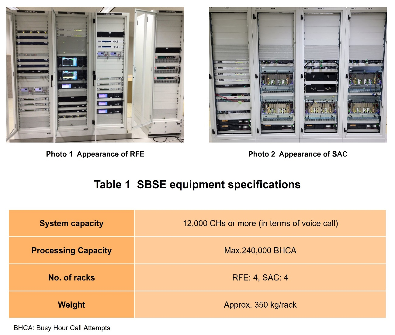
SBSE consists of Radio Frequency Transmitting and ...
Open
SBSE consists of Radio Frequency Transmitting and Receiving Equipment (RFE) that performs amplification and frequency conversion of radio waves transmitted and received to and from the satellite, and a Satellite Access Controller (SAC) that performs modulation/demodulation and radio control [4]. Photo 1 shows the appearance of RFE and Photo 2 shows the appearance of the SAC. Table 1 shows the equipment specifications for SBSE.
2.1 RFE Configuration
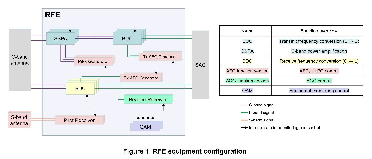
RFE is equipment consisting of general-purpose, rack-mounted radio equipment. The RFE configuration is shown in Figure 1.
RFE is equipment that relays communication signals mainly between the SAC and C-band*2 antennas, and consists of right- and left-handed circularly polarized*3 paths for both transmission and reception. The transmitter systems consist of Block Up Converters (BUCs) that convert the L-band*4 transmitting signal received from the SAC to the C-band frequency, and Solid State Power Amplifiers (SSPAs) that amplify the BUC output signal and transmit it to the C-band antenna. The receiver systems consist of Block Down Converters (BDCs) that convert the C-band received signal from the Low Noise Amplifiers (LNAs)*5 in the C-band antenna to the L-band frequency. In addition, RFE has the Auto Frequency Compensation (AFC) for frequency compensation, and Up Link Power Control (ULPC)*6 and Automatic Gain Control (AGC)*7 functions for gain*8 compensation in the satellite link section via a geostationary satellite. The Operation And Maintenance (OAM)*9 function, which monitors and controls RFE, runs on a general-purpose server.
2.2 SAC Configuration
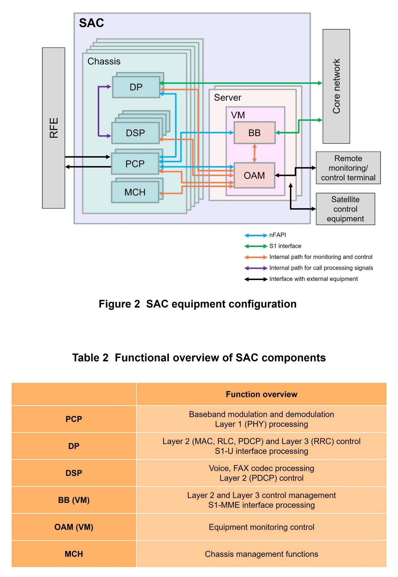
An SAC is equipment consisting of cards*10 mounted on a chassis*11 and a general-purpose server. A configuration of the SAC is shown in Figure 2 and a functional overview of the SAC components is shown in Table 2.
An SAC also consists of Physical Channel Processors (PCPs) that process PHYsical layer (PHY)*12, which is mainly Layer 1*13 of the LTE system; Data plane Processors (DPs) that perform Layer 2*14 (Medium Access Control (MAC)*15, Radio Link Control (RLC)*16, Packet Data Convergence Protocol (PDCP)*17) control, Layer 3*18 (Radio Resource Control (RRC)*19) control, and S1-U*20 interface processing; Digital Signal Processors (DSPs) that perform codec processing*21 for voice and fax and Layer 2 (PDCP) control; BaseBands (BBs) that perform Layer 2 and Layer 3 control management and S1-Mobility Management Entity (MME)*22 interface processing; an OAM that performs SAC equipment monitoring and control; and a Micro-TCA Carrier Hub (MCH) that performs chassis management.
An SAC also has an interface to receive satellite orbit information of N-STAR e for use in WIDESTAR III from the satellite control equipment via an IP network.
2.3 SBSE Features
WIDESTAR III requires high reliability because of its critical role as a lifeline and as a business continuity plan for companies in times of disaster. It also requires economical equipment development to enable lower communication fees to expand its use during normal times.
1) Reliability
- The BUC, SSPA, and BDC that make up the RFE transmission and reception paths have a redundant N+1 configuration*23. When a component failure occurs in either the right or left plane of polarization*24, the system switches to the standby system so that transmission and reception of communications carriers are not interrupted and services can be continued. All other components have a redundant ACTive (ACT)/StandBY (SBY) configuration*25 (Fig. 1).
- In the SAC, the cards (PCP, DP, DSP) that process radio communication control in the chassis have a redundant ACT/ACT configuration*26 that enables load balancing processing among cards with the same functions. In the event of a card failure, the remaining cards (groups), including cards in a different chassis, can take over processing while performing load balancing processing (Fig. 2).
The BB and OAM running on a Virtual Machine (VM)*27 on the server have a redundant ACT/SBY configuration that makes full use of open-source, general-purpose high availability*28 technology, enabling service continuity by switching to the standby system immediately in the event of failure.
In addition, one set of SBSE is located in each of the two stations, so that even if only one station is operating due to damage to the station or its facilities, or during construction of base station facilities, SBSE has enough capacity to accommodate and handle all the traffic required for the system.
2) Economic Efficiency
- RFE combines general-purpose components to achieve cost-effective equipment development.
- An SAC makes maximum use of call processing protocol applications compliant with international standardized LTE systems and runs customized software on general-purpose hardware and servers. The open interface network Functional Application Platform Interface (nFAPI)*29 is used for communication control processing between PCP-DP and PCP-BB, and for monitoring control processing between PCP-OAM to reduce the developmental costs. Furthermore, running BB and OAM software on the same VM on the server reduces hardware costs (Fig. 2).
- C-band: Name for the frequency band between 4 and 8 GHz. WIDESTAR III uses the 6/4 GHz frequency band.
- Right- and left-handed circular polarization: A form of radio propagation in which the electric (magnetic) field rotates circularly (right- or left-handed) in the direction of propagation.
- L-band: Name for the frequency band between 0.5 and 2 GHz.
- LNA: Equipment that is used to amplify a signal directly after it is received by the antenna. Very little noise is added to the signal in amplification, so even very weak signals can be amplified with little distortion.
- ULPC: A function that adjusts the transmission power of a base station so that the received power of a satellite mobile station, which fluctuates due to daily changes in the satellite orbit and rain attenuation, etc., remains constant.
- AGC: A function that maintains the received power of a base station at a constant power level, which fluctuates due to daily changes in satellite orbit and rain attenuation, etc.
- Gain: The ratio of the power obtained at the output terminal of an amplifier (output power) to the input power when a signal is input to the amplifier at a certain power (input power).
- OAM: Functions for maintenance and operational management in a network.
- Card: A component panel or board such as a power amplifier, frequency converter, modulation and demodulation processing function.
- Chassis: An enclosure into which component panels and boards are inserted and mounted in a rack.
- PHY: The physical layer, which performs modulation and demodulation of radio frequency carriers and coded data modulation for wireless signal transmission.
- Layer 1: The first layer (physical layer) in the OSI reference model.
- Layer 2: The second layer (data link layer) in the OSI reference model.
- MAC: A sublayer in Layer 2, which performs radio resource allocation, data mapping, and retransmission control, etc.
- RLC: A sublayer in Layer 2, which performs retransmission control, duplicate detection, and sequencing, etc.
- PDCP: A sublayer in Layer 2, which performs ciphering, integrity protection, header compression, etc.
- Layer 3: The third layer (IP layer) in the OSI reference model. In this article, refers to the RRC protocol.
- RRC: Layer 3, which controls radio resources for radio communications.
- S1-U: Interface connecting the base station to the core network on the U-Plane side.
- Codec processing: The compression or decoding of video or audio data using an encoding scheme.
- S1-MME: Interface connecting the base station to the core network on the C-Plane side.
- N+1 configuration: A system configuration in which one standby system is provided for multiple active systems, and when a failure occurs in one of the active systems, the system switches to the standby system.
- Plane of polarization: The plane determined by the propagation direction of a radio wave and the direction of the electric field.
- ACT/SBY configuration: A configuration in which two devices with the same functions are installed, one of which is operated as the active system and the other as the standby system. In the event of a device failure in the active system, processing is immediately taken over by the standby system to prevent service outages.
- ACT/ACT configuration: A configuration in which multiple devices with the same functions are operated simultaneously. In normal times, processing speed is improved through parallel processing, and in the event of a failure, the failed device is disconnected and the processing is taken over by remaining devices to prevent service outages.
- VM: A computer created in a virtual manner by software.
- High availability: Technology that minimizes service downtime due to system failures, etc. and enables stable service provision.
- nFAPI: A communication protocol between MAC and PHY specified by the Small Open Forum.
-
WIDESTAR III uses LTE as its communications system to build ...
Open
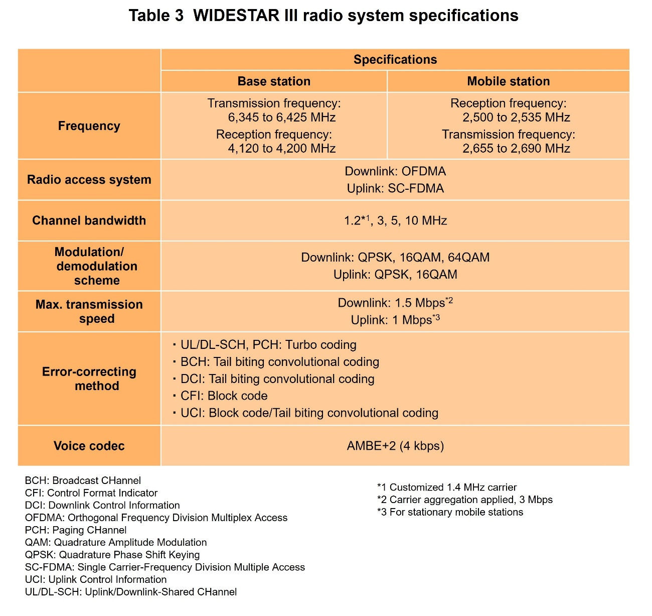
WIDESTAR III uses LTE as its communications system to build an efficient and advanced system. Table 3 shows the main radio system specifications.
Effectively utilizing the LTE system and the transponder performance of the N-STAR e digital high-throughput communications satellite [5], which is equipped with an ultra-large deployable antenna, makes it possible to achieve the wide channel bandwidth and multi-level modulation and demodulation schemes shown in Table 3. That enables significant increase in data rates over those of WIDESTAR II. Compared to the data rate of WIDESTAR II, the downlink data rate is approximately four times faster (384 kbps → 1.5 Mbps), and the uplink data rate is approximately seven times faster (144 kbps → 1 Mbps). Furthermore, when carrier aggregation*30 is used, the downlink communication speed can be doubled to a maximum of 3 Mbps.
In addition, the multi-bearer*31 function enables simultaneous use of voice/fax and data communications services, improving convenience.
On the other hand, since the LTE system is an international standard for terrestrial cellular systems, the following issues had to be addressed to apply it to WIDESTAR III.
- (a) The round-trip propagation delay from the satellite mobile station (hereinafter referred to as the “mobile station”) to the base station equipment (SAC) via the geostationary satellite is approximately 250 ms, longer than the LTE radio frame*32.
- (b) Because the satellite irradiation beam (cell) radius is large, approximately 400 km, the propagation delay difference within the beam is longer than the subframe*33 required for Random Access (RA) preamble*34 transmission in LTE.
- (c) Inclined geostationary satellite orbits*35 cause propagation delay times to vary by up to approximately 15 ms over the course of a day.
- (d) Although there is a need to expand communication capacity in times of disaster, Voice over LTE (VoLTE)*36 requires a higher transmission rate than G.729a*37 (8 kbps) used in WIDESTAR II.
- (e) The fax service, which is highly demanded by marine users, had to be continued, but it is not defined as a QoS class identifier*38 in the LTE system.
To solve these issues, we customized the communications system and developed SAC functions.
3.1 Addressing Issues in LTE System Expansion
1) Time Alignment (TA) Extension
TA is a control to adjust the uplink transmission timing of each mobile station according to the propagation delay to the SAC to match the uplink signal transmitted from each mobile station in a cell to the SAC reception timing. The 250 ms round-trip delay from the mobile station to the SAC via the geostationary satellite is longer than the 10 ms radio frame length of the LTE system, so customization is required to ensure proper TA for mobile stations accessing from different locations within a large service area. As shown below, NTT DOCOMO developed a TA function for uplink signaling from call connection to call disconnection to achieve stable WIDESTAR III service provision.
- The N-STAR e satellite used by WIDESTAR III is an inclined geostationary orbit satellite with a maximum inclination of 7 degrees. The SAC maintains representative values of propagation delay times for each beam calculated from the satellite positions and the position and shape of the satellite beams. The position of the satellite is periodically obtained from the ephemeris information*39 of the N-STAR e transmitted from the satellite control equipment to the SAC, and the representative value of propagation delay time of each beam is recalculated each time according to the time-varying position of the satellite. The calculated representative value is reported by the SAC to the mobile station as an information element of Master Information Block (MIB)*40 to which parameters have been newly added. Based on the broadcast system information*41, the mobile station sends Random Access CHannel (RACH)*42 matched to the timing that the SAC is able to receive the channel.
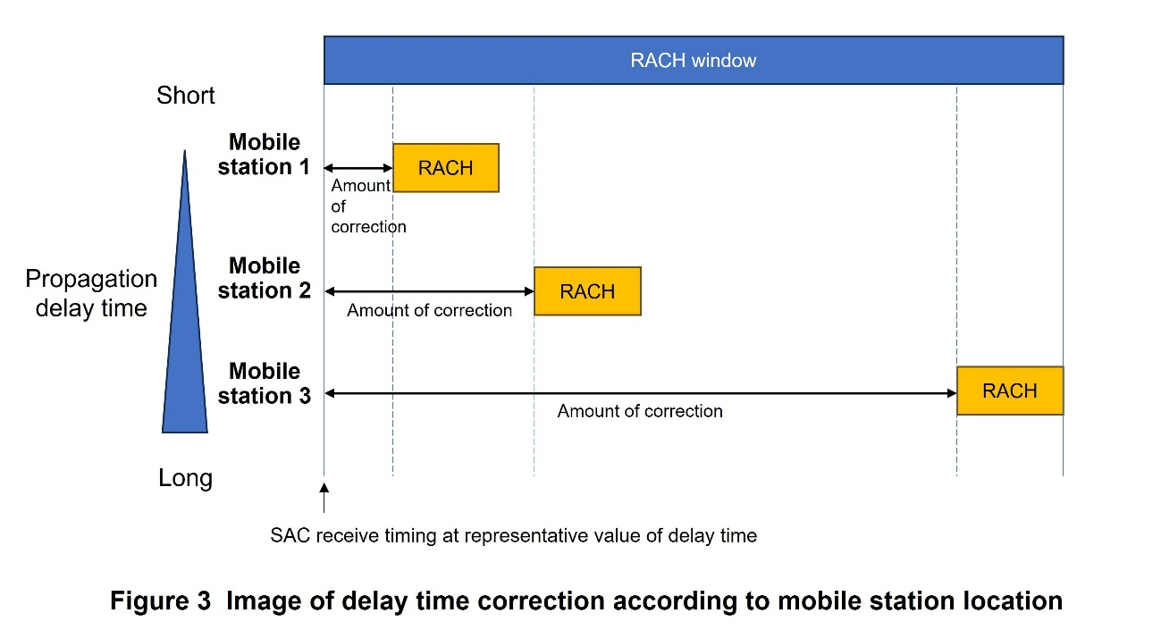
- However, because the beam radius of the N-STAR e is large (150 to 400 km), the propagation delay time between the mobile station and the satellite differs from the representative value reported by the SAC depending on the location of the mobile station. When the SAC receives a RACH, it calculates the uplink timing deviation from the representative value and notifies the mobile station of the amount of time correction to the representative value in the RACH response*43 to adjust the propagation delay in accordance with the mobile station location in the cell. However, the satellite beam radius is larger than the LTE cell radius and the uplink timing is affected by propagation delay due to the curvature of the earth's surface, which means that the correction range in LTE standard specifications cannot cover the uplink timing deviation. Therefore, by extending the correction specification values based on the service area and beam location and shape, the adaptation of the LTE system to WIDESTAR III is achieved. Figure 3 shows an image of the delay time correction according to the mobile station location in a cell. The mobile station continues the call connection by sending a signal at a timing that uses the correction amount received in the RACH response.
- While the mobile station continues to communicate, the satellite's orbital position may change over time and the mobile station itself may move, so the correction value set at the time of call connection may not be sufficient to maintain communication. Therefore, to adjust the propagation delay correction value, the SAC monitors the uplink reception timing during communication and notifies the mobile station of the difference in the correction amount with TA command*44. The mobile station accumulates the differences in the received correction amounts and communicates using the appropriate uplink timing correction value until the end of the call.
2) RACH Window Extension
The propagation delay between a mobile station and a base station varies from a representative value of propagation delay time up to approximately 10 ms, depending on the location of the mobile station, even within the same cell. The RACH transmission specified in the LTE system takes a maximum of three subframes (3 ms) [6]. Therefore, a RACH from a mobile station cannot be received unless a sufficient reception window*45 is provided, so WIDESTAR III extends the RACH reception window (RACH window) time. On the other hand, if the RACH window is extended uniformly to all beams, Physical Uplink Shared CHannel (PUSCH)*46 resources are reduced, resulting in lower uplink throughput. Therefore, in WIDESTAR III, the RACH window can be set according to the position and shape of each beam, and the RACH transmission period is set longer than the standard specification value to improve resource efficiency issue.
3) Hybrid Automatic Repeat reQuest (ARQ)*47 Function Removed
The round-trip delay time between the mobile station and the SAC is approximately 250 ms, so the ACKnowledgement (ACK)*48 response wait timer (8 ms) of the Hybrid ARQ function, which is an error correction standard in the LTE system, always times out and cannot function. WIDESTAR III is a line-of-sight*49 based communications system, and its radio interface has been simplified by removing the Hybrid ARQ function after evaluating that sufficient channel quality can be obtained even if the Hybrid ARQ function is disabled through radio performance evaluation and verification.
3.2 Addressing Issues in Adapting to Service Requirements
1) Response to Voice Service Requests
Due to the greater severity and longer duration of recent disasters, there is a need to expand voice communications capacity and the number of simultaneous connections during disasters. Therefore, Advanced Multi-Band Excitation (AMBE)+2*50 (4 kbps) was adopted as the voice codec for the radio link (between the mobile station and SAC) to enable voice communications with only 1 Resource Block (RB)*51 allocation. This enables voice communications services with less bandwidth than VoLTE standard codecs (in NTT DOCOMO's case, Adaptive Multi-Rate Wide Band (AMR-WB)*52 (12.65 kbps) is used at the start of VoLTE service) and increases the number of simultaneous connections. Since standard codecs are not used, AMBE+2 codec conversion is performed in the SAC and communication is mutually performed with the core network*53 via G.711*54, allowing the core network to process without being aware of the difference between voice and fax communications, as described below.
For Dual-Tone Multi-Frequency (DTMF)*55 tones, transmission within the AMBE+2 codec is supported in the radio link. An SAC performs conversion between DTMF using the AMBE+2 codec and DTMF using the Real-time Transport Protocol (RTP) Event*56 used in VoLTE, so that both the core network and mobile stations can process DTMF data without being aware of the difference between codecs.
2) Adoption of Fax Protocol (T.38*57)
Based on customer requests in the WIDESTAR II service, WIDESTAR III adopts Facsimile over IP (FoIP) (T.38), which enables transparent fax transmission, as the fax protocol for the radio link. An SAC has a function to switch from voice to fax mode when fax communication is detected, and a protocol conversion function to convert fax communication using T.38 in the radio link to deemed voice*58 over G.711 in the SAC. By doing so, the core network can perform fax transmission as voice communication without being aware that it is fax communication, and fax communication not defined as a QoS class identifier in the LTE system is enabled.
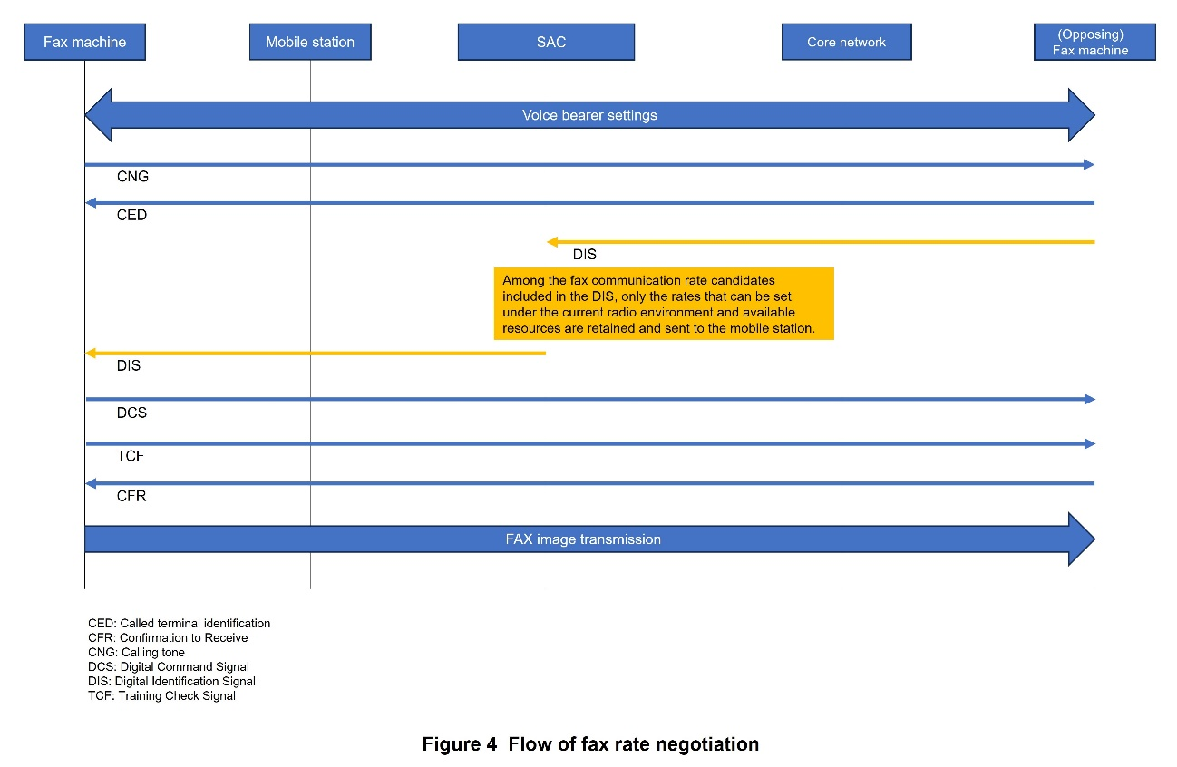
In addition, for selecting the transmission rate when sending faxes, an SAC is equipped with a function that intervenes in the rate negotiation that is normally performed only between devices sending and receiving faxes in order to set the fax rate according to the radio quality status, thereby achieving efficient radio transmission of faxes. Figure 4 illustrates the rate negotiation process for faxes.
- Carrier aggregation: A technology that achieves high-speed transmission by using multiple carriers for simultaneous transmission and reception to increase bandwidth.
- Multi-bearer: Simultaneous establishment of multiple bearers, which are logical packet transmission paths set up between core equipment, base stations, and terminals.
- Radio frame: A unit of data transmission over a radio link. A radio frame consists of multiple slots (or subframes) on the time axis, and each slot consists of multiple symbols on the time axis.
- Subframe: A unit of radio resources in the time domain consisting of multiple Orthogonal Frequency Division Multiplexing (OFDM) symbols.
- Preamble: The first signal sent by a UE when performing random access control such as during initial connection.
- Inclined geostationary satellite orbit: An orbit in which the requirements for the orbit position of a geostationary satellite against the ground are relaxed to reduce the fuel consumption of the satellite and extend its service life. The satellite follows a figure-8 orbit relative to the earth's surface.
- VoLTE: A method for making voice calls over an LTE network, which is an IP-based network.
- G.729a: A voice coding scheme widely used in IP telephony, etc.
- QoS class identifier: An indicator of the quality of communication (priority, guaranteed bandwidth, and acceptable data loss rate) required in an LTE network.
- Ephemeris information: Detailed satellite orbit information including position and time information.
- MIB: Broadcast system information that is sent simultaneously from a base station to terminals, and contains physical layer information such as the system bandwidth of a cell.
- Broadcast system information: Essential system information (including regulatory, common channel, random access channel information, and so on required for executing the procedure for connecting mobile terminals to cells) to be broadcasted within a cell.
- RACH: A signal used by a terminal that has not established a connection with the base station to request a connection.
- RACH response: A response signal from the base station to the RACH received from the terminal.
- TA command: Timing adjustment information to match the transmission/reception timing between a base station and a terminal.
- Reception window: The interval on the time axis where the desired signal is expected to be received.
- PUSCH: Shared channel used to transmit data in the uplink.
- Hybrid ARQ: A technique that compensates for errors in received signals through a combination of error-correcting codes and retransmission.
- ACK: A receive acknowledgment signal whereby a receiving node can tell the sending node whether or not the data was successfully received (decoded).
- Line-of-sight: Describes an environment where there are no obstacles between the transmitter and receiver, allowing them to communicate via direct waves.
- AMBE+2: A narrowband voice codec developed by DVSI, Inc., in the U.S. It is used in satellite phones and digital transceivers.
- RB: The smallest unit of radio resource allocation that bundles several consecutive subcarriers.
- AMR-WB: A broadband audio codec standardized by International Telecommunication Union Telecommunication Standard Sector (ITU-T) and 3GPP.
- Core network: A network consisting of packet switching equipment, subscription information management equipment, etc. A mobile terminal communicates with the core network via a radio access network.
- G.711: A standard for speech coding established by ITU-T, used for transmission of speech signals in fixed telephone networks. A fixed bit rate of 64 kbit/s.
- DTMF: A method to send audio tones uniquely allocated to each button of a telephone set. Alternatively called tone-signals or push-tones.
- RTP Event: A method of transmitting tone signals on a voice transmission channel such as DTMF as digital information in a dedicated signal format on the RTP protocol.
- T.38: A communication protocol established by ITU-T for sending and receiving faxes over IP networks. Also called FoIP.
- Deemed voice: A method of transmitting signal information (DTMF, fax, etc.) as digital information over a voice transmission channel without converting it to a dedicated signal format.
-
WIDESTAR III must be able to respond flexibly to traffic demands ...
Open
WIDESTAR III must be able to respond flexibly to traffic demands in the service area during a disaster.
In addition, since WIDESTAR III uses the same frequency band as WIDESTAR II, system migration from WIDESTAR II to WIDESTAR III must be achieved with minimal service impacts.
To meet these requirements, WIDESTAR III has an online station configuration data update function and system maintenance functions.
4.1 Online Station Configuration Data Update Function
The N-STAR e [2] satellite used for WIDESTAR III can change its relay bandwidth and beam on orbit through digital beamforming*59. Therefore, the SAC and satellites can work together to change the frequency resource allocation of beams and cells, enabling frequency resources to be added online as needed for areas with high traffic demand such as disaster areas. Through an interface with the satellite control equipment, the SAC receives the allocated frequency for each beam set to the satellite and can flexibly change some or all of the set frequencies online by updating station configuration data*60. When changing the allocated frequency set for a satellite, the station configuration data for the frequency to be allocated for each beam is prepared in advance and stored in the SAC, making it possible to update the frequency settings of the satellite and SAC at the same time.
NTT DOCOMO also developed a Network Planning Support Tool (NPST) to assist station configuration data preparation so that maintenance personnel can add cells and set parameters according to traffic demand and satellite link conditions. In WIDESTAR III, the number of beams has been significantly increased from 4 to 64 compared to the WIDESTAR II, and beams can be composed of multiple cells, which makes parameter setting more complex. The NPST enables maintenance personnel to efficiently and accurately create cell parameter settings for each beam.
4.2 System Maintenance Functions
To prepare for the unavailability of a base station (SAC) due to construction work on the base station facilities or in the event of a disaster, a system maintenance control function has been implemented to transfer mobile stations on standby or in communication to another base station (SAC) as a maintenance function unique to the satellite system. The WIDESTAR III system utilizes the cell selection*61 and handover*62 controls of the LTE system to achieve system maintenance control by simply performing online updates to the station configuration data for system maintenance.
1) Migration of Standby Mobile Stations to another SAC
The maintainer updates the station configuration data online for system maintenance, so that the neighboring cell information reported in System Information Block (SIB) 5*63 of the source SAC is only the allocated cell of the destination SAC, and the cell selection parameters are changed. The mobile station on standby in the source SAC autonomously reselects a cell in the destination SAC by reading the broadcast system information from the source SAC and performs the Inter-SAC transition. At the same time, the source SAC sets regulatory information to prevent mobile stations that have performed the Inter-SAC from returning to the source SAC.
2) Migration of Mobile Stations in Communication
Mobile stations in communication judge quality degradation based on the threshold value (Event A2) received from the SAC, as with the LTE system [6]. When the mobile station sends a report for cell quality deterioration in the area to the SAC, the SAC instructs the mobile station to measure the quality of candidate cells for the handover destination. In WIDESTAR III system maintenance control, the threshold value (Event A2) of the source SAC is pseudo raised and notified to the mobile station to encourage the mobile station to measure the quality of surrounding cells and perform handover to the cell of the destination SAC, thereby realizing autonomous Inter-SAC transition of calls in communication.
- Beamforming: A technique to increase/decrease the antenna gain in a particular direction by forming a directional pattern on the antenna through controlling the amplitude and phase of multiple antennas. The beamforming described in this article is realized by digital control.
- Station configuration data: Data that specifies the operating conditions of the equipment, environmental settings, cell parameters, etc.
- Cell selection: Selection by the terminal of a cell to be used for communication among multiple cells observable from the terminal.
- Handover: Switching the cell to which the communicating terminal is connected.
- SIB 5: An SIB in which the surrounding cell information necessary for cell reselection is sent from the base station to the terminal as broadcast system information.
-
This article has described the development of new satellite ...
Open
This article has described the development of new satellite base station equipment for WIDESTAR III. The development of this equipment has enabled the LTE over GEO Satellite system*64 to support faster radio communications speeds to meet the need for faster data communications and to succeed the existing WIDESTAR II service.
NTT DOCOMO will continue to provide safe and secure communications to customers as a means of communication during emergencies and disasters and improve service quality to meet a wide variety of customer needs.
- LTE over GEO Satellite System: An LTE-based mobile communications system provided via a geostationary communications satellite.
-
REFERENCES
Open
- [1] K. Yamamoto et al.: “Overview of WIDESTAR II Mobile Satellite Communications System and Service,” NTT DOCOMO Technical Journal, Vol. 12, No. 2, pp. 37-42, Sep. 2010.
 https://www.docomo.ne.jp/english/binary/pdf/corporate/technology/rd/technical_journal/bn/vol12_2/vol12_2_037en.pdf (PDF format:1,235KB)
 - [2] K. Kamogawa et al.: “Overview of WIDESTAR III System and Services,” NTT DOCOMO Technical Journal, Vol. 26, No. 2, Oct. 2024.
https://www.docomo.ne.jp/english/corporate/technology/rd/technical_journal/bn/vol26_2/006.html - [3] N. Okubo et al.: “Overview of LTE Radio Interface and Radio Network Architecture for High Speed, High Capacity and Low Latency,” NTT DOCOMO Technical Journal, Vol. 13, No.1, pp. 10-19, Jun. 2011.
https://www.docomo.ne.jp/english/binary/pdf/corporate/technology/rd/technical_journal/bn/vol13_1/vol13_1_010en.pdf (PDF format:934KB) - [4] H. Tahara, M. Nakamura, T. Kanekiyo, K. Kamogawa: “Development of WIDESTAR III Base Station Equipment,” 2024 IEICE General Conference, B-3-27, Mar. 2024 (in Japanese).
- [5] M. Inoue: “NTN's Vision for Beyond 5G/6G,” 2024 IEICE General Conference, BI-11-01, Mar. 2024 (in Japanese).
- [6] 3GPP TS36.211 V18.0.1: “Evolved Universal Terrestrial Radio Access (E-UTRA); Physical channels and modulation,” Apr. 2024.
- [1] K. Yamamoto et al.: “Overview of WIDESTAR II Mobile Satellite Communications System and Service,” NTT DOCOMO Technical Journal, Vol. 12, No. 2, pp. 37-42, Sep. 2010.

