
Special Articles on 3GPP Release 18 Standardization Activities (2)
Overview of 5G Core Network Advanced Technologies in 3GPP Release 18 —System Architecture—
3GPP Release 18 SA
Jari Mutikainen, Malla Reddy Sama and Riccardo Guerzoni
DOCOMO Communications Laboratories Europe GmbH
Yoshitaka Hatanaka, Junpei Uoshima and Atsushi Minokuchi
6G-Tech Department
Abstract
In 3GPP Rel-18, functional improvements were made and new technical areas were added to 5GC architecture centered about Extended Reality and Media services (XRM), deterministic communications, network slicing, RNAA, and intent driven management. This article provides an overview of 5GC Advanced technologies that have been enhanced in 3GPP Rel-18.
01. Introduction
-
Continuing from enhancements made in 3rd Generation Partnership ...
Open

Continuing from enhancements made in 3rd Generation Partnership Project (3GPP) Release 16 and Release 17, the architecture of the 5G Core network (5GC)*1 originally formulated in Release 15 was further enhanced in various fields in Release18, which is the initial release of 5G-Advanced. In particular, functional improvements were made and new technical areas were added to support Extended Reality (XR)*2 and media services such as Virtual Reality (VR)*3 and Augmented Reality (AR)*4, deterministic communications*5, network slicing*6, Resource owner-aware Northbound Application Program Interface Access (RNAA)*7, and intent driven management.
- In extended reality and interactive media services that require high data rate and low-latency communications, the Quality of Service (QoS)*8 can be improved especially in congestion*9 conditions. In addition, power consumption of the XR device can be reduced.
- In timing services and deterministic communications, the existing time synchronization function was enhanced and a service providing timing to User Equipment (UE) was introduced. In addition, deterministic communications was introduced in the Transport Network (TN)*10. Furthermore, 3GPP Release 18 introduces support of IETF DetNet, where 5G System (5GS)*11 can be configured to act as a DetNet router.
- In network slicing, functions were enhanced for dealing with temporarily available network slices and replacing a congested slice with an alternative slice, and a function concerning a policy of connecting to a necessary network slice only when needed was enhanced.
- RNAA adds a mechanism of permitting API access under the authorization of the user affected by API usage to the Common API Framework (CAPIF)*12 that manages northbound API*13 access. This mechanism, which was based on Internet Engineering Task Force (IETF)*14 OAuth 2.0*15, was introduced in 5GC.
- Intent driven management is a management method that drives the system so as to provide a desired state (intent) without having to have detailed knowledge of network operations. Specifications related to this management method were enhanced.
This article provides an overview of these enhancements.
- 5GC: The fifth-generation core network specified by 3GPP for 5G access technologies.
- XR: Generic name for technology that provides new experiences by fusing virtual space and real space.
- VR: Virtual reality.
- AR: A technology that superposes digital information on video of the real world such that it actually appears to be part of the scene to the user.
- Deterministic communications: Communications that guarantee arrival of the data within a permitted delay period.
- Network slicing: One form for achieving next-generation networks in the 5G era by logically dividing the network into units of services corresponding to use cases, business models, etc.
- RNAA: API invocation scenario that requires the API user to obtain authorization from the resource owner (see *117).
- QoS: Quality of a communications service. Bandwidth and latency are typical indicators.
- Congestion: A state where communication requests are concentrated in a short time period and exceed the processing capabilities of the network, thereby obstructing communications.
- TN: The network connecting the access network with the core network or the network interconnecting equipment within each of those networks.
- 5GS: The 5G network system, consisting of the core network, RAN, and communications devices.
- CAPIF: A 3GPP framework that provides common functions for exposing northbound APIs.
- Northbound API: An API that provides mobile network functions and resources to a 3rd party operator.
- IETF: A standardization organization that develops and promotes standards for Internet technology.
- OAuth 2.0: A mechanism to authorize system operations for a legitimate client. RFC 6749.
-
In Rel-18, a number of extensions have been introduced for increasing ...
Open
In Rel-18, a number of extensions have been introduced for increasing the processing efficiency of “XR services (AR/VR services)” and “interactive media services” requiring high data rates and low-latency communication. These are conversational services based on Web Real-Time Communication (WebRTC)*16 or Internet protocol Multimedia Subsystem (IMS)*17 using Realtime Transport Protocol (RTP)*18 /Secure RTP (SRTP)*19 for media transport.
In many cases, media transport requires stable periodicity in traffic burst*20. For example, in video calls or video streaming services that use H.264*21 or H.265*22 video codecs, video frames are transmitted at fixed intervals (such as 60 frames per second). Here, each video frame is independent of other frames (as in the case of an I-frame*23) or each expresses the difference between the previous and future frame (as in the case of a P-frame*24 or B-frame*25).
In the 5GS QoS framework before Rel-18, all Protocol Data Units (PDUs)*26 that transmit these frames use the same QoS parameters set for each QoS flow*27 in processing.
In Rel-18, to improve radio resource scheduling in the Next Generation-Radio Access Network (NG-RAN)*28, different types of QoS processing (different priority settings, etc.) can be used for individual PDUs that transmit such frames. In this way, the NG-RAN can recognize the content and importance of application PDUs and the user experience of the service can be improved particularly at times of congestion.
Another functional improvement made in Rel-18 relates to power consumption in XR devices such as smart glasses. Specifically, the power consumption of UE can be reduced by adjusting connected-mode Discontinuous Reception (DRX)*29 parameters based on media stream periodicity and burstiness.
2.1 Optimization of Radio Resource Scheduling in XR Applications
In Rel-17 and prior releases, the QoS flow was the finest granularity for QoS differentiation. In Rel-18, the purpose of PDUs within a media stream can be identified and the handling of QoS in NG-RAN (i.e., radio resource scheduling) can be changed for each PDU within a single QoS flow.
1) DownLink (DL) Direction
In the DL direction of the media stream, the instructions received from the Application Function (AF)*30 via the Control Plane (C-Plane)*31 and the content of the PDU received from the application server via the User Plane (U-Plane)*32 are used as a basis for PDU identification and classification by the User Plane Function (UPF)*33.
(a) PDU set QoS parameters
Using the Nnef_AFsessionWithQoS service*34, AF provides media-stream PDU set QoS parameters (PDU Set Delay Budget (PSDB), PDU Set Error Rate (PSER), PDU Set Integrated Handling Information (PSIHI), and Protocol Description) to the Network Exposure Function (NEF)*35.
Among these PDU set QoS parameters, PSDB, PSER, and PSIHI are provided to the NG-RAN via the Policy Control Function (PCF)*36 and Session Management Function (SMF)*37 and used in radio resource scheduling. Protocol description, meanwhile, is provided to UPF via PCF and SMF.
The PSDB parameter sets the maximum delay for transmitting all PDUs belonging to a single PDU set and PSER sets the maximum error rate of the PDU set, while PSIHI indicates to NG-RAN whether all of the PDUs in the PDU set are needed by the application. Here, for the case in which NG-RAN must discard one PDU within a PDU set due, for example, to congestion, NG-RAN can discard the remaining PDUs as soon as one PDU in the PDU set is lost in order to release radio resources.
The protocol description includes detailed information that is needed by UPF for identifying stream PDUs and building a PDU set from PDUs. A PDU set is an aggregate of PDUs that expresses a video frame, etc.
Parameters may differ between the UpLink (UL) and DL. As in previous releases, AF also provides NEF with other types of information related to the media stream. For example, this could be the IP 5 tuple*38 used for identifying the stream.
(b) RTP header extension
In Rel-18, 3GPP specified a new RTP header extension (hereinafter referred to as “3GPP RTP header extension”) in TS26.522 [1] for PDU set identification. An RTP sender such as an application server uses the 3GPP RTP header extension for PDU marking in the RTP media stream. This extension can indicate the PDU set sequence number, PDU sequence numbers within the PDU set, end of the PDU set, size of the PDU set, number of PDUs within the PDU set, and PDU Set Importance (PSI). Additionally, if the application server should not be using the 3GPP RTP header extension, TS26.522 [1] describes guidelines on a method for PDU identification by UPF for common video codecs (e.g., H.264 and H.265) transmitted by RTP/SRTP.
To determine the transport protocol*39 and codec used in the stream and whether the 3GPP RTP header extension is included, UPF also uses the protocol description received from AF (via NEF, PCF, and SMF). After identifying the PDU set, UPF marks the PDU set in the GPRS Tunneling Protocol for User Plane (GTP-U)*40 header for NG-RAN.
In the 3GPP RTP header extension, PSI indicates importance relative to other PDU sets in the QoS flow. The importance of audio PDUs is usually set higher than other PDUs. In a congestion state, NG-RAN may use PSI to discard a PDU with low importance. The PSDB and PSIHI values may also be considered in determining whether to discard.
2) UL Direction
In the UL direction, UE can receive through a Non-Access Stratum (NAS)*41 message a UL protocol description from SMF (via the Access and Mobility management Function (AMF)*42) and can use that description to identify the PDU set. In addition, NG-RAN can configure the UE in relation to Data Radio Bearer (DRB)*43 discard operations and provide discard timer values to the UE. The UE, then, at the time of transmission, if one PDU in the PDU set is discarded because its discard timer has expired, will discard all PDUs within that PDU set.
2.2 Functional Extensions to UE Power Saving in XR Services
1) DRX Overview
The DRX function is a mechanism for saving power on the UE. With this mechanism, the UE is periodically activated to receive signals and put into sleep at other times to extend the UE's battery life. It can be applied either in Idle mode (Idle-mode DRX) or Connected mode (Connected-mode DRX).
Idle-mode DRX is used when the UE, which is in Idle mode, must be open to radio signals due to the possibility of a paging signal*44 arriving from the network. Extended DRX (eDRX) is a functional extension to Idle-mode DRX targeting ultra-low-power-consuming Internet of Things (IoT) devices. It can extend the sleep cycle of Idle-mode DRX by up to several hours depending on the application's allowable paging delay.
Connected-mode DRX, on the other hand, is applied when the UE application is in the process of communicating such as when receiving a media stream from the application server. The radio in UE, though being in a Radio Resource Control (RRC)*45 connected state, is in a sleep state for most of the time, and the UE can monitor for DL data from the application server only when it is periodically awaken by the DRX cycle timer*46. If the DRX cycle timer expires and wakes up the UE, the UE stays awake only for the duration set by the DRX on-duration timer*47 unless the UE receives data from NG-RAN. On the other hand, once data has been received, the UE starts the DRX inactivity timer*48. These DRX timers are set in the UE by NG-RAN.
2) Extensions to Connected-mode DRX
In Rel-18, Connected-mode DRX has been extended—the network can adjust DRX timers based on the periodicity of the XR media stream. In addition, the DRX cycle timer can be set in accordance with the video frame rate. For example, given a frame rate of 60 frames per second, the DRX cycle timer can be set to the non-integer value 16.66 milliseconds = 50/3 milliseconds.
In addition, the UPF may be instructed to measure at an N6*49 interface (an interface between UPF and the application server) the jitter*50 in DL media stream periodicity. This jitter measured by UPF is sent to NG-RAN on the C-Plane (via SMF) so that the NG-RAN can use that value to adjust the DRX on-duration timer. After indicating the planned periodicity of the stream, the AF can activate jitter measurement via NEF (using the Nnef_AFsessionWithQoS service).
The UPF can indicate the end of the data burst in the GTP-U header of the last PDU of the DL video frame. Using this indication, NG-RAN can return the UE to sleep mode before the expiration of the DRX inactivity timer. In addition, the UPF can use the protocol description or 3GPP RTP header extension described above or both to identify the PDU that marks the end of the data burst.
In the UL direction, the UE can provide NG-RAN with support information (UL periodicity and jitter) for each QoS flow.
2.3 Support for ECN Marking for L4S
Low Latency, Low Loss, Scalable Throughput (L4S) is a new scalable congestion control mechanism defined in IETF RFC 9331 [2]. This mechanism generates and transmits an L4S Explicit Congestion Notification (ECN) marking*51 on the IP layer to notify of network congestion before a queue within the network becomes full and the need arises to discard packets. The data transmission side detects the L4S ECN marking and reduces its bit rate.
The L4S mechanism uses the ECN method on the IP layer, but in contrast to the ECN method initially defined in IETF RFC 3168 with respect to Transmission Control Protocol (TCP)*52, it performs ECN marking more frequently and enables the data transmission side to respond smoothly. Use of L4S can reduce network congestion and latency.
To use L4S in the network, L4S-compatible traffic and other non-L4S-compatible traffic must be processed on different queues. In Rel-18, specifications establish different QoS flows for L4S-compatible traffic (e.g., Quick User Datagram Protocol Internet Connections (QUIC)*53) and other non-L4S-compatible traffic. In addition, the data transmission side indicates L4S ECN compatibility with respect to traffic on the IP layer.
The NG-RAN monitors for congestion, and in the event that congestion occurs, generates an ECN marking on the IP layer and sends it to the UE. Alternatively, NG-RAN reports the buffer state to UPF via the GTP-U header of a UL packet, and the UPF executes an ECN marking on the IP layer and sends it to the UE. In either case, the UE on receiving an ECN-marked IP packet performs an echo back*54 of the ECN mark to the sender. For example, in the case that QUIC is used as the transport protocol of the media stream, the UE's QUIC stack*55 indicates to the sender that ECN markings have been received by returning the cumulative ECN counter of the QUIC layer to the sender (application, etc.). In this way, the sender becomes aware of congestion and adjusts its data rate until the received ECN counter stops reporting an increase in its value.
- WebRTC: A mechanism for real-time communication of audio, video, and other files between Web browsers and mobile applications, etc., via APIs, and an open standard whose source code is publicly available.
- IMS: A subsystem that provides IP multimedia services (e.g., VoIP, messaging, presence) on a 3GPP mobile communications network. Session Initiation Protocol (SIP) is used for the calling control protocol.
- RTP: A protocol defined by IETF for real-time distribution of audio, video or other such media.
- SRTP: A protocol defined by IETF for securely delivering media such as audio and video in real time.
- Traffic burst: Data that flows within a short period of time.
- H.264: An encoding scheme for video data.
- H.265: A coding scheme for video data succeeding H.264.
- I-frame: Intra-coded frame of video data in which certain pictures are encoded independently of each other without using frame predictive coding.
- P-frame: A frame that cannot be reproduced without referring to an I-frame.
- B-frame: A frame that cannot be reproduced without referring to an I-frame and P-frame.
- PDUs: Units of data for protocol processing.
- QoS flow: Minimum granularity of QoS transport processing in 5GC.
- NG-RAN: A RAN connecting to the 5G core network using New Radio (NR) or Evolved Universal Terrestrial Radio Access (E-UTRA) as radio access technology.
- DRX: Intermittent reception control used to reduce power consumption in UE.
- AF: A network function that provides an application.
- C-Plane: The part of the signal sent and received in communications that is involved in control.
- U-Plane: The part of the signal sent and received in communications, which contains the data sent and received by the user.
- UPF: A transmit/receive processing function for user data in a 5G core network.
- Nnef_AFsessionWithQoS service: A service provided by NEF (see *35) that accepts QoS-related control from AF.
- NEF: A logical node for providing some of the functions possessed by a 3GPP system for 5G to parties outside the 3GPP domain.
- PCF: An NF in 5GC responsible for policy control, such as QoS and billing control.
- SMF: The 5GC network function that manages sessions.
- IP 5 tuple: Generic name for five types of information—destination IP address (see *86), destination port number, source IP address, source port number, and protocol number—stored in the IP header and TCP (see *52)/UDP (see *60) header.
- Transport protocol: Refers to RTP or SRTP when used within the protocol description. Otherwise, it generally refers to the protocol used on the transport layer.
- GTP-U: A tunneling protocol used by radio base stations and devices in the core network to transmit user data.
- NAS: A function layer in the protocol stack between the UE and core network.
- AMF: A logical node that accommodates base stations (gNB) and provides mobility control and other services.
- DRB: A bearer on a radio link where U-plane data flows.
- Paging signal: A radio signal for notifying a mobile terminal that is in standby state of an incoming call or network information update.
- RRC: Layer 3 protocol for controlling the radio resources.
- DRX cycle timer: A timer that sets the Connected-mode DRX period.
- DRX on-duration timer: In one DRX cycle of Connected-mode DRX, a timer that sets the UE's active time.
- DRX inactivity timer: In one DRX cycle of Connected-mode DRX, a timer that sets the time for the UE to reenter a sleep state after receiving signals while active.
- N6: A reference point between a UPF and a DN.
- Jitter: Fluctuations in delay time in signals, user data, etc.
- L4S ECN marking: The setting of information in an IP packet for using L4S.
- TCP: An upper-layer protocol commonly used on the Internet. It features high reliability compared to UDP.
- QUIC: An upper-layer protocol of IP/UDP used on the Internet.
- Echo back: The process of returning received information in the form it was received.
- QUIC stack: Functions for handling QUIC.
-
At 3GPP, Rel-16 supported the integration of 5GS and Institute ...
Open
At 3GPP, Rel-16 supported the integration of 5GS and Institute of Electrical and Electronics Engineers Time-Sensitive Networking (IEEE TSN)*56 networks, which provide deterministic communications as part of IEEE 802*57 networks.
One important constituent technology throughout IEEE TSN specifications is time synchronization. Rel-16 included support for an IEEE 1588 [3] Ethernet bridge*58 protocol profile called generic Precision Time Protocol (gPTP)
*59 (IEEE 802.1AS [4]). Rel-17, meanwhile, introduced support of PTP that uses User Datagram Protocol (UDP)*60 /IP that is used, for example, in commercial audio/video applications. In either Rel-16 or Rel-17, 5GS functions as a PTP instance*61 and delivers a PTP time synchronization message to the PTP client. In addition, Rel-17 introduced a separate method of delivering a 5G reference time to the UE via a radio interface without using PTP to avoid the use of a local GNSS in the UE. This method is also called “5G Access Stratum Time distribution (ASTI).” At this time, the UE can deliver a 5G reference time to an application within the UE by some original means.The following describes improvements in time synchronization and other functional enhancements to deterministic communications in Rel-18. Support for IETF DetNet has also been introduced in Rel-18 enabling 5GS to function as a DetNet router.
3.1 Improvements in Time Synchronization in 5GS
In Rel-18, a number of improvements were added to time synchronization functions introduced in previous releases.
1) Resilience of 5G Timing Services
Timing services in 5GS depend on synchronization of the UE, gNodeB (gNB)*62, and UPF internal clocks. This synchronization can be achieved by deploying TN to support a PTP communication protocol (e.g., ITU-T G.8265.1 [5]) between gNB and UPF or using a local Global Navigation Satellite System (GNSS)*63 as a time source for gNB and UPF.
However, in the method using a local GNSS, potential degradation of 5GS internal clocks due to problems in GNSS signal performance may affect the accuracy of 5G timing services. Some applications used, for example, in the finance sector and a smart grid*64 are more sensitive to such degradation in timing accuracy.
(a) Provision of clock quality acceptance criteria
In Rel-18, a means for an AF to provide clock quality acceptance criteria for 5GS time synchronization services is specified. The AF, for example, manages one or more UE devices that depend on timing information in 5GS time synchronization services, and providing clock quality acceptance criteria to 5GS makes it possible to monitor whether those UE devices are obtaining suitably precise timing information. In the case that such criteria are being provided, 5GS monitors the state of network time synchronization in the 5G internal clocks of NG-RAN and UPF. Here, attributes of the state of network time synchronization targeted for monitoring include clock precision, traceability to Coordinated Universal Time (UTC)*65, traceability to GNSS, frequency stability, and master time source*66.
Acceptance criteria for clock quality are provided from the AF to the Time Sensitive Communication and Time Synchronization Function (TSCTSF)*67 and to NG-RAN via PCF and AMF. In NG-RAN, thresholds are set beforehand for the attributes of the network time synchronization state. In the event that any one of these attributes exceeds its threshold, NG-RAN compares the acceptance criteria within the UE's context with the current state of time synchronization of the 5G internal clocks within NG-RAN. Then, if the acceptance criteria are not satisfied, NG-RAN sends a “not acceptable” notification to the UE.
If the UE has not yet connected, this notification is sent to the UE by a RRC signal next time it connects to the network. To make a RRC-Idle or RRC-Inactive UE aware of a degraded or improved clock state, NG-RAN changes the event ID every time the clock state changes and notifies the UE of the event ID via the System Information Block (SIB)*68. Now, if the UE on the basis of that notification recognizes that the event ID has been updated from the previously stored value, it reconnects to the network and learns the new clock state provided by NG-RAN via a RRC signal.
Furthermore, when using ASTI, the UE notifies the application within it that a “not acceptable” notification has been received and that the current clock quality does not satisfy service standards.
(b) Provision of clock quality metrics*69
As an alternative to clock quality acceptance criteria, the AF can instruct 5GS to provide the UE with clock quality metrics (in other words, actual values of individual attributes of the network time synchronization state within NG-RAN). The method of using these clock quality metrics depends on the UE.
(c) Method of notifying network time synchronization state attributes to TSCTSF and TSCTSF operation
Two mechanisms are defined for NG-RAN to notify TSCTSF of the current attributes of the network time synchronization state. One notifies TSCTSF via Operations, Administration, and Maintenance (OAM)*70 while the other first notifies AMF via Next Generation Application Protocol (NGAP)*71 non-UE associated signaling and then notifies TSCTSF from AMF via the Namf_Communication service*72. The UPF notifies TSCTSF of the clock state via OAM or SMF and PCF.
Based on the attributes so notified, TSCTSF determines which UE is being affected and whether the acceptance criteria of the clock quality indicated by the AF is being satisfied. Here, to determine whether a UE is being affected, TSCTSF must obtain a UE location report from AMF. If the UE is being accommodated by a NG-RAN node*73 with a degraded clock state, AMF sends TSCTSF a UE identifier. Then, TSCTSF that has now determined that acceptance criteria is not being satisfied will either report the state of the time synchronization service to AF or, in the case that the UE is part of a PTP instance, will temporarily delete the UE's PTP port from the PTP instance.
2) Coverage Area of 5G Timing Services
As previously described, Rel-17 supports time synchronization services by either of two methods. In one method, 5GS operates as a PTP instance, and in the other, 5G reference time is delivered to the UE via a radio interface from NG-RAN (a method called ASTI). In Rel-18, both methods have been improved by making it possible for AF to provide a coverage*74 area for time synchronization services.
The AF indicates the coverage area to NEF as a “Tracking Area (TA)*75 list” or a “geographical area that NEF converts to a TA list.” TSCTSF requests AMF for a UE's position. Whenever AMF notifies TSCTSF that a UE has moved into or outside the coverage area, TSCTSF respectively enables or disables the UE's time synchronization services. In short, if the UE is part of a PTP instance, the UE's PTP port is activated or temporarily deactivated, and if not, ASTI is enabled or disabled. TSCTSF also notifies AF of the UE's service state (that is, whether the PTP port or ASTI has been activated or deactivated).
In addition, given the possibility that the granularity of the Registration Area (RA)*76 is exceeded and AMF does not recognize the UE location, AMF aligns the requested coverage area with the UE's current registration area. This means that all TAs within the RA will be handled as a time synchronization coverage area even if some TAs within the RA have not been requested by AF.
3) 5G Timing Services Controlled by User Subscriber Information
In Rel-17, AF controls UE time synchronization services. Specifically, as defined in 3GPP TS29.522 [6], AF can perform this control using the Nnef_TimeSyncExposure service in the case of PTP or the Nnef_ASTI service in the case of ASTI.
In Rel-18, time synchronization services can be determined by user subscriber information. In this case, the service interface from AF is disabled for a specific user. Subscriber data is stored in Unified Data Management (UDM)*77 and includes time-synchronization service parameters the same as those provided by AF. Service data in the UDM database consists of two parts: time synchronization subscriber data that indicates PTP service parameters to TSCTSF and access/mobility subscriber data that indicates ASTI to AMF.
In Rel-18, the operator can set the range that can be taken by service parameters used by AF in a service request for UE. For example, there are cases in which AF can request a coverage area only from those coverage areas allowed by UDM user subscriber information. This can be verified by TSCTSF when AF sends service parameters to 5GS.
3.2 Integration of TSN Functions Deployed in TN with 5GS
Rel-18 supports the integration of TSN functions deployed in the TN with 5GS. The purpose of this integration is to enable deterministic communications in the TN by indicating QoS requirements of a 5GS QoS flow transmitting deterministic traffic and traffic characteristics (such as burst arrival time, bust interval, and required maximum latency) to the TN. The interface between 5GS and TN is TSN User-Network Interface (UNI) defined in IEEE Std 802.1Q [7] and IEEE P802.1Qdj [8].
5GS functions as a Central User Controller (CUC) *78 entity*79 with respect to the Central Network Controller (CNC)*80 entity. This 5GS CUC entity is collocated with the SMF of the corresponding PDU session*81. It obtains stream requirements from SMF when the PDU session is established and passes them to the TN CNC. The CUC entity also communicates with the TSN Talker/Listener implemented in the NG-RAN Access Network TSN Talker/Listener (AN-TL)*82 and the UPF Core Network TSN Talker/Listener (CN-TL)*83. Here, TSN parameters between SMF/CUC and AN-TL and CN-TL are transmitted by a TL-Container defined in Annex M.2 of TS23.501 [9], where the data model of the TL-Container is based on IEEE Std 802.1Q [7], IEEE P802.1Qdj [8], and IEEE Std 802.1CBdb [10].
The AN-TL and CN-TL functions are options in NG-RAN and UPF. When supported, AN-TL and CN-TL execute a stream conversion under the control of TN CNC. On performing such a stream conversion, AN-TL and CN-TL use the group destination MAC address*84 allocated by TN CNC (a single MAC address allocated from the group MAC address space allocated by TN CNC) as a stream destination MAC address. The TN can identify a stream using this destination MAC address and can also apply different types of processing to each identified stream.
In addition to the stream conversion method, the TN can identify a stream by using the N3*85 tunnel IP address*86, or provided that the mask-and-match stream identification function defined in section 6.8 of IEEE Std 802.1CBdb [10] is supported, by using the GTP-U header N3 Tunnel Endpoint Identifier (TEID)*87 and QoS Flow ID (QFI)*88.
3.3 Allocation of Radio Resources to Deterministic Streams
In Rel-16, functions based on traffic patterns, that is, Burst Arrival Time (BAT)*89 and periodicity of deterministic TSN streams, were introduced to support the allocation of radio resources (such as timing in a configured grant*90 in the UL direction and semi-persistent scheduling*91 in the DL direction) in NG-RAN. In Rel-17, the same functions became general-purpose functions with respect to any deterministic streams even in the case that 5GS is not operating as a TSN bridge.
Now, in Rel-18, a functional improvement was made to enable NG-RAN to provide AF with a BAT offset value. In this way, BAT could be aligned with the stream's next opportunity for a burst transmission expected at NG-RAN. This functional improvement targets applications that must satisfy very low latency (e.g., 2 milliseconds). The BAT offset value provided by NG-RAN to AF is a relative value indicating the difference with the original BAT received by NG-RAN from AF using an Nnef_AFsessionWithQoS service request. It is sent to AF by the Nnef_AFsessionWithQoS_Notify service*92, and on so being notified, the application adjusts data transmission timing according to the offset value.
Both a proactive method and reactive method have been defined for determining the BAT offset value. In the proactive method, NG-RAN provides the BAT offset value to SMF when responding to the establishment of a QoS flow or to a change request. In the reactive method, NG-RAN measures traffic on the U-Plane. If NG-RAN judges that QoS-flow latency requirements cannot be satisfied due to burst timing, NG-RAN determines the BAT offset value so as to shorten the time between the traffic burst arrival time and the time of the next expected opportunity for a burst transmission.
In the same way, NG-RAN can notify AF of traffic periodicity after adjustment to align the traffic burst period with the expected interval between successive transmission opportunities. Periodicity after adjustment is provided to AF together with the BAT offset value. The application then adjusts data transmission timing according to those values.
3.4 IETF DetNet
1) IETF DetNet Overview
IETF DetNet defines architecture for transmitting an IP data flow (hereinafter referred to as “IP flow”) designated for real-time applications with very low data loss rate, guaranteed bandwidth, and bounded delay. DetNet functions are similar to IEEE TSN, but while IEEE TSN is Layer 2*93 technology, IETF DetNet is Layer 3*94 technology, which means it is applicable to a wide area network consisting of multiple subnets*95. Additionally, while 5GS TSN operates in an Ethernet PDU session, DetNet operates in an IP PDU session, so UE does not need to support an Ethernet PDU session with DetNet.
2) 5GS Control by DetNet Controller
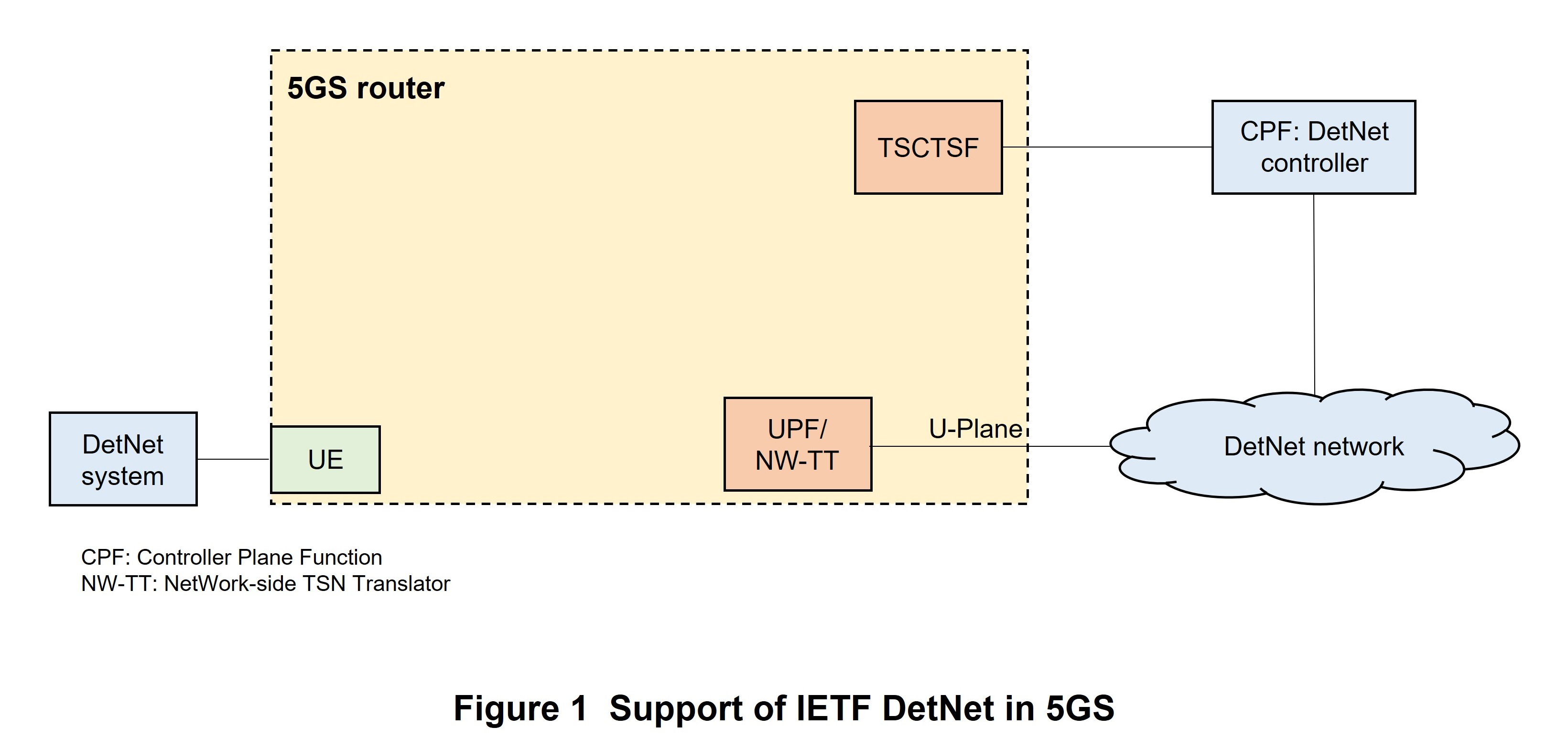
To support deterministic communications based on IETF DetNet, 5GS functions as a logical DetNet transit router (hereinafter referred to as “5GS router”) as defined in IETF RFC 8655 [11] (Figure 1). Here, to control 5GS IP flow processing, TSCTSF exposes the RESTCONF*96 (IETF RFC 8040 [12]) or Network Configuration Protocol (NETCONF)*97 (IETF RFC 6241 [13]) control interface to the DetNet controller. The interface data model is based on the IETF DetNet YANG model*98. It has been extended at 3GPP as defined in Annex B of TS29.565 [14].
Using a control interface exposed by TSCTSF in this way, the DetNet controller can collect 5GS-router connection information (e.g., IP address allocated to the PDU session or IPv6 prefix*99, range of IPv4*100 addresses that can arrive via the PDU session or IPv6 prefix, interface identifier of each port) and configure network topology*101. Here, an interface identifier is unique within the 5GS router—it can be generated, for example, within 5GS based on the port number.
On collecting the above information, the DetNet controller uses a control interface as described above to send IP-flow traffic characteristics and QoS requirements to the 5GS router. The DetNet controller also uses the “5GS-node-max-latency” parameter unique to 3GPP to notify the IP flow within the 5GS router of the maximum latency.
TSCTSF determines the corresponding PDU session based on the interface identifier indicated by the controller or, in the case that an interface identifier from the controller cannot be used, based on the source IP address of the IP flow, and sends information to the corresponding PCF for each PDU session. The internal 5GS procedures (involved with PCF, SMF, UPF, etc.) are nearly the same as the procedures used when 5GS functions as a TSN bridge except when the UPF and UE traffic filter is based not on the Ethernet header but on the IP 5 tuple.
- IEEE TSN: A series of standards specified by IEEE for handling data streams that must be transmitted without exceeding allowable values for delay and jitter or a network constructed on the basis of those standards.
- IEEE 802: A committee in IEEE that specifies standards for Local Area Networks (LANs) and Metropolitan Area Networks (MANs).
- Ethernet bridge: A node for transferring frames on Ethernet.
- gPTP: A protocol profile of IEEE 1588 (PTP) standardized by IEEE 802.1AS.
- UDP: An IP upper-layer protocol used as standard on the Internet.
- PTP instance: Entity configured with necessary settings to process PTP.
- gNB: A radio base station for NR radio access.
- Local GNSS: Generic name of a satellite positioning system such as GPS or Quasi-Zenith Satellite System.
- Smart grid: A power distribution network that incorporates radio sensors in the power system to autonomously monitor, control, and optimize the supply side and demand side in real time.
- UTC: Time on which standard time around the world is based.
- Master time source: A device that provides timing information.
- TSCTSF: In a network configuration in which 5GS is not integrated with IEEE TSN, TSCTSF manages 5GS time synchronization and deterministic communications services.
- SIB: Information broadcast from a base station to UE including information needed to determine cell selection, PLMN selection, etc.
- Metrics: Quantitative values of target attributes or states based on fixed criteria.
- OAM: Functions for maintenance and operational management in a network.
- NGAP: An upper-layer protocol used in an interface between a base station and the core network in 5GS.
- Namf_Communication service: A service given by AMF to a core network function so that information can be exchanged with a base station.
- Node: Equipment that realizes a certain set of functions in the network.
- Coverage: An area that can transmit/receive radio signals or use specific services.
- TA: A unit that indicates a location consisting of one or more cells.
- RA: A unit configured by one or more TAs indicating the locations of mobile terminals managed on the network.
- UDM: A database that stores and provides information such as subscription data, location information, and session information in 5GC.
- CUC: In an IEEE TSN network, a node that receives stream requirements from a node transmitting a stream and that conveys those requirements to CNC.
- Entity: A structural element that provides functionality within a logical architecture.
- CNC: A node that controls a bridge in an IEEE TSN network.
- PDU session: A logical connection between the UE and data network.
- AN-TL: A function placed at a base station on the boundary with TSN to enable use of TSN deployed in TN.
- CN-TL: A function placed at UPF on the boundary with TSN to enable use of TSN deployed in TN.
- MAC address: A 12-digit fixed physical address allocated to an Ethernet board.
- N3: An interface for transferring user data between the radio access network and core network.
- IP address: A unique identification number allocated to each computer or communications device connected to an IP network such as an intranet or the Internet.
- TEID: A connection path address identifier used in GTP protocol.
- QFI: QoS flow identifier.
- BAT: The time that a data burst will arrive.
- Configured grant: The allocation of UL data transmission resources beforehand by the base station to the user.
- Semi-persistent scheduling: The allocation of DL data transmission resources beforehand by the base station to the user.
- Nnef_AFsessionWithQoS_Notify service: A service provided by NEF for notifying AF of the occurrence of a control-related event after control involving QoS has been accepted from AF.
- Layer 2: The second layer (data link layer) in the OSI reference model.
- Layer 3: The third layer (IP layer) in the OSI reference model.
- Subnets: Subdivisions of a network.
- RESTCONF: A protocol for controlling network devices.
- NETCONF: A protocol for controlling network devices.
- IETF DetNet YANG model: A YANG model is a data model specified by IETF DetNet.
- IPv6 prefix: Part of an IPv6 address indicating the group that that address belongs to.
- IPv4: The Internet protocol that is currently used. Address resources are managed as 32-bit numbers.
- Network topology: The configuration of a network.
-
At 3GPP, network slicing features have been provided since ...
Open
At 3GPP, network slicing features have been provided since Rel-15 specifications. Network slicing separates logical network segments even if service requests from different customers are competing with each other, enabling a variety of business needs to be satisfied. Following the Rel-15 formulation, improvements were studied at the Global System for Mobile Communications Association (GSMA)*102 to enable the network to control the use of resources for a network slice according to the customer and the results of that study were compiled [15].
In Rel-18, multiple aspects of network slicing were taken up including service continuity such as when a network slice or network slice instance*103 cannot provide a PDU session or when the application's performance requirements cannot be satisfied. Network slices that have a limited valid period are also supported. This function includes a method for avoiding a sudden release of the PDU session and gracefully terminating a network slice. It can also be applied to a network slice with a long valid period. The following describes improvements made to the network slicing mechanism in Rel-18.
4.1 Support of Network Slice Management in the Case of Temporary Availability or Occurrence of an Unexpected Network Operation
Network slicing is deployed to satisfy the needs of various customers. For example, an operator can deploy a slice for all UEs within an area or for a limited number of UEs. In addition, a network slice may be deployed for only a limited amount of time (e.g., deployment of a slice for customers inside a stadium during a match). Optimized network processing is also required in such a case. Furthermore, the network must be able to deal with unexpected situations such as congestion and be able to execute a careful recovery procedure conforming to the agreed upon Service Level Agreement (SLA)*104 without impacting other slices. For these reasons, the following mechanisms were defined in Rel-18.
1) Optimized Processing for Network Slices with Limited Availability
There is a type of network slice that can be used by all UEs or a limited number of UEs for only a limited amount of time (a temporarily or periodically active time period) known beforehand by the network based on OAM, subscriber information, etc. At 3GPP, the valid period for Single-Network Slice Selection Assistance Information (S-NSSAI)*105 that can be managed by the network and UE has been defined to reduce signal load in relation to network-slice registration management and transitions in the session management state.
The AMF uses OAM settings or information received from UDM or the Network Slice Selection Function (NSSF)*106 as a basis for informing the UE of one or more S-NSSAI valid periods within the Configured NSSAI via a Registration Accept message or a UE Configuration Update procedure.
Based on the valid-period information accompanying S-NSSAI within the Configured NSSAI, the UE, in the case that the valid period indicates that the S-NSSAI cannot be used, will not include that S-NSSAI in the Requested NSSAI*107. In the case that the UE completes the registration procedure within the S-NSSAI valid period and the S-NSSAI is already an Allowed NSSAI*108 or part of a Partially Allowed NSSAI*109, then, if the valid period indicates that the S-NSSAI cannot be used, the UE deletes that S-NSSAI from the locally stored Allowed NSSAI or Partially Allowed NSSAI and locally releases the PDU session associated with the S-NSSAI.
Likewise, AMF, given that the valid period indicates that the S-NSSAI cannot be used, locally deletes the S-NSSAI from Allowed NSSAI or Partially Allowed NSSAI (in other words, deletes it without sending signals to the UE). Additionally, if a PDU session has been established for that S-NSSAI, AMF requests SMF to release the PDU session.
If the valid period indicates that the S-NSSAI cannot be used again, the UE deletes that S-NSSAI from the locally stored Configured NSSAI.
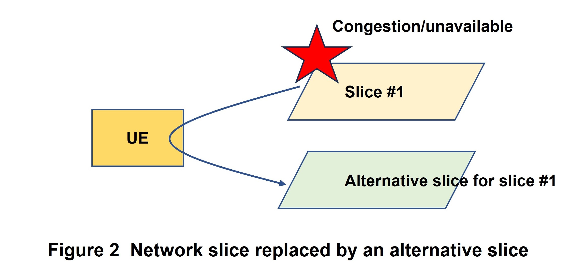
2) Support of Network Slice Replacement
If an S-NSSAI becomes unusable (for whatever reason) or congestion exists, the network slice replacement function temporarily replaces that S-NSSAI with an Alternative S-NSSAI (Figure 2).
In such situations of an unavailable S-NSSAI or a state of congestion, NSSF, PCF, and OAM detect an event that has occurred. As examples of operations that take place after detection, NSSF on making the detection will send AMF an S-NSSAI network slice availability notification, while PCF on making the detection will send AMF a policy notification related to access and mobility, for example. Such notifications from NSSF, PCF, or OAM will include an Alternative S-NSSAI to replace the S-NSSAI. The AMF then records S-NSSAI and Alternative S-NSSAI mapping and notifies the UE of slice replacement by a UE Configuration Update message or Registration Accept message.
On establishing a PDU session on the Alternative S-NSSAI, the UE notifies AMF of both S-NSSAI and Alternative S-NSSAI, and AMF selects an appropriate SMF using SMF Selection Subscription data of the replaced S-NSSAI. The SMF then continues to establish the PDU session using the Alternative S-NSSAI and Data Network Name (DNN)*110 received from the UE.
In the case that the replaced S-NSSAI becomes usable again (if, for example, congestion eases), AMF deletes the mapping from the replaced S-NSSAI to the Alternative S-NSSAI and deletes that Alternative S-NSSAI from Allowed NSSAI and Configured NSSAI so that the UE can be reconfigured to again use the replaced S-NSSAI (using, for example, the UE Configuration Update message or the next registration procedure).
4.2 Support for Network Slice Usage Control
In 5GS specifications up to Rel-18, the telecommunications operator could not control the timing at which the UE registers or deletes registration with a network slice or the timing at which a PDU session is established or released. For example, the operator could not have a UE register with a certain network slice only when a connection with that network slice is actually necessary. Additionally, in settings for the User equipment Route Selection Policy (URSP)*111, even if a Home Public Land Mobile Networks (HPLMN)*112 slice corresponding to the application is included in the UE's connection options (in URSP), there has been no method for the serving PLMN (i.e., HPLMN or Visited PLMN (VPLMN)*113) to route the UE to a slice desired by that serving PLMN.
For this reason, Rel-18 specifies a new mechanism in which AMF determines slice usage policy for one or multiple UE network slices to control that or those network slices and configures the UE using this information together with Configured NSSAI. This network-controlled slice usage policy is provided to the UE together with Configured NSSAI for the serving PLMN using the Registration Accept or UE Configuration Update command. The UE, in turn, internally stores the received slice usage policy.
This slice usage policy includes settings that enable the UE to register with a network slice using the network only when an application within the UE needs to transfer data using that network slice. It is also possible as an option to include a registration-release inactivity timer for releasing the network slice after the last PDU session associated with S-NSSAI has been released.
4.3 Service Area Restrictions
In general, a network slice is defined at the granularity of each TA, but in the case of a private network or a commercial IoT application, it is convenient for the telecommunications operator to be able to use a network slice having geographically limited availability that does not necessarily agree with the existing TA boundary. It is the responsibility of the operator to configure network-slice resources at the TA cells that the slice should be able to use and to set the area that cannot be used (area with no resources).
The AMF receives Network Slice Area of Service (NS-AoS)*114 as information related to network-slice availability (meaning that a network slice cannot be used at some of the TA cells) from OAM. It sets the UE using S-NSSAI location availability information (described below) derived from the NS-AoS information received from OAM. It also monitors the S-NSSAI usage conditions and applies NA-AoS particularly to UEs not supporting S-NSSAI location availability information.
S-NSSAI location availability information defines an additional limitation in the use of S-NSSAI in a TA in which network slice availability does not match the TA's boundary. A UE that has received S-NSSAI location availability information can request an S-NSSAI only when S-NSSAI location availability information indicates that the S-NSSAI can be used at the cell in which the UE currently resides.
- GSMA: An organization active in the development of the entire mobile telecommunications industry consisting of mobile network operators and members related to the mobile telecommunications industry from around the world.
- Network slice instance: NFs composing a network slice, and associated resources (e.g., computing resources, storage resources, networking resources).
- SLA: The agreement between the service provider and the service consumer.
- S-NSSAI: An identifier for network slices, used by 5GC.
- NSSF: NF that selects the network slice to be used by the subscriber.
- Requested NSSAI: A network slice requested by the UE to be used at the time of the registration procedure.
- Allowed NSSAI: A network slice that the network allows to be used at the time of the registration procedure.
- Partially Allowed NSSAI: A network slice that the network allows to be used in some TAs within RA.
- DNN: The destination of UE communications. The identifier of the data network that the UE connects to via the core network.
- URSP: Policy used by UE for selecting an appropriate route for each traffic pattern.
- HPLMN: The operator where the user is a subscriber; their home operator.
- VPLMN: The subscriber's roaming-destination operator.
- NS-AoS: An area in which network slicing can be used.
-
5.1 CAPIF
Open
3GPP specifies NEF and Service Capability Exposure Function (SCEF)*115 as functions of the northbound API that releases functions and resources possessed by a mobile network to third-party providers and provides a variety of service APIs. CAPIF is a uniform framework for solving common issues such as the publishing and management of those APIs, security aspects, etc. The drafting of CAPIF specifications proceeded at the 3GPP Technical Specification Group Service and System Aspects (TSG SA)*116 Working Group (WG) 6 (hereinafter referred to as “SA6”) and CAPIF was standardized in Rel-15.
5.2 Purpose of Introducing RNAA
RNAA is an optional function related to CAPIF authorization proposed by NTT DOCOMO and standardized in Rel-18. This function enables CAPIF to request authorization from the resource owner*117 to use resources. As one example of a use case, we can consider a situation in which the user of an online game would like to play the game under comparable circuit speeds as the user's opponent. The RNAA function makes it possible to request the opponent (resource owner) for a change in QoS that controls communication bandwidth.
RNAA is based on the OAuth 2.0 mechanism standardized by IETF. By applying an authorization protocol widely used in Web services to CAPIF, RNAA aims to broaden the use of CAPIF technology to meet the needs of various third-party providers and developers.
Although several authorization grant methods using RNAA have been specified in Rel-18, this article describes RNAA based on a typical authorization code grant method.
5.3 RNAA Architecture
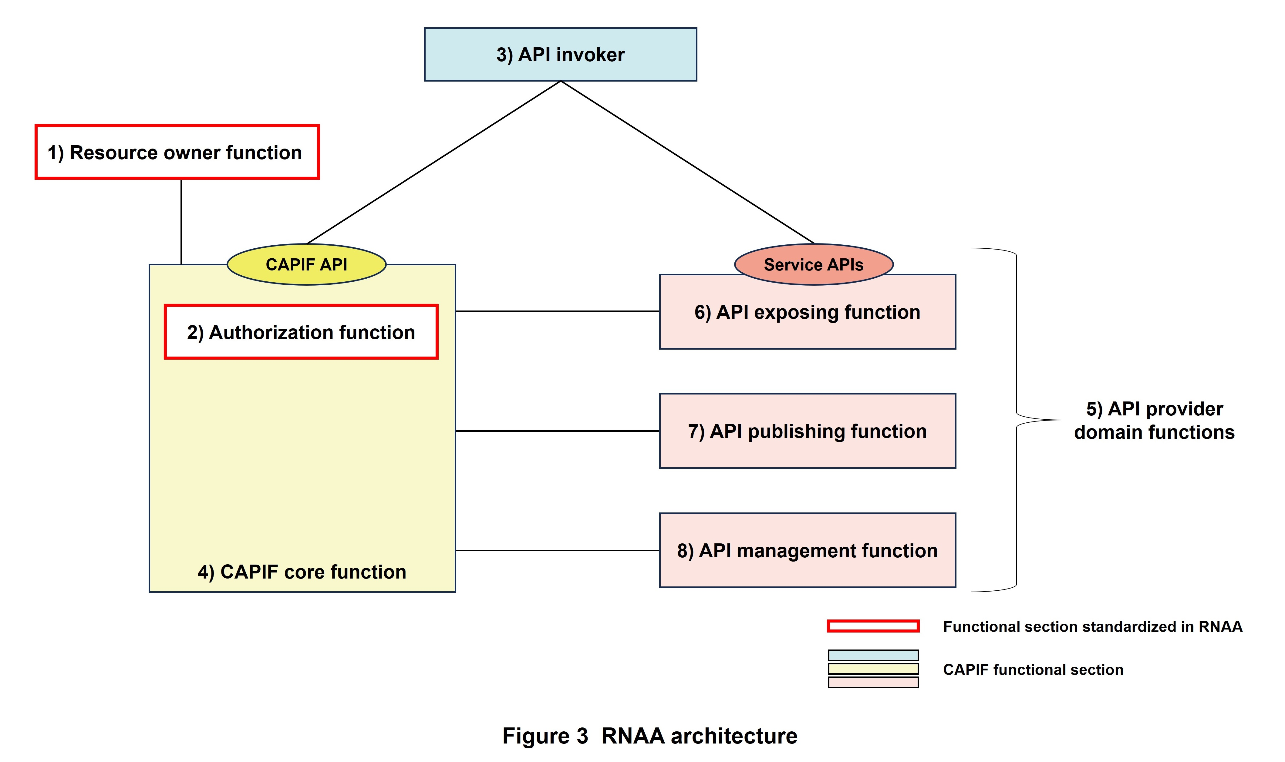
Typical RNAA architecture is shown in Figure 3. Here, the resource owner grants the API invoker permission to access its resources through RNAA. Technical details for CAPIF and RNAA can be found at Refs. [1], [2], and [9].
The functions making up this RNAA architecture are summarized below.
1) Resource Owner Function
This is an RNAA functional section that links with the authorization function within the CAPIF core function for managing authorization requests made to the resource owner. It corresponds to the resource owner in OAuth 2.0.
2) Authorization Function
This is an RNAA functional section that links with the resource owner function and authorizes the issuing of an authorization code. It corresponds to the authorization server in OAuth 2.0.
3) API Invoker
This is an invoker of the CAPIF API or service API. It refers to the network operator or third-party applications on UE and corresponds to the client in OAuth 2.0.
4) CAPIF Core Function
This is a CAPIF functional section that provides the CAPIF API and plays a central role in a variety of functions provided by CAPIF such as authentication and authorization of API invokers, registration of service APIs, and policy management. Authorization management in RNAA is handled by the 2) authorization function within the CAPIF core function.
5) API Provider Domain Functions
These functions provide service APIs and make up a CAPIF functional section commonly referred to as an “API exposing function,” “API publishing function,” and “API management function.”
6) API Exposing Function
This is a CAPIF functional section that accepts an API call from an API invoker. It corresponds to the resource server in OAuth 2.0.
7) API Publishing Function
This is a CAPIF functional section that publishes service API information to the CAPIF core function so that an API invoker can use a service API.
8) API Management Function
This is a CAPIF functional section that manages published service APIs such as by auditing service API calling logs and monitoring the state of service APIs.
Functions 7) and 8) above are given here as reference information irrespective of the following description.
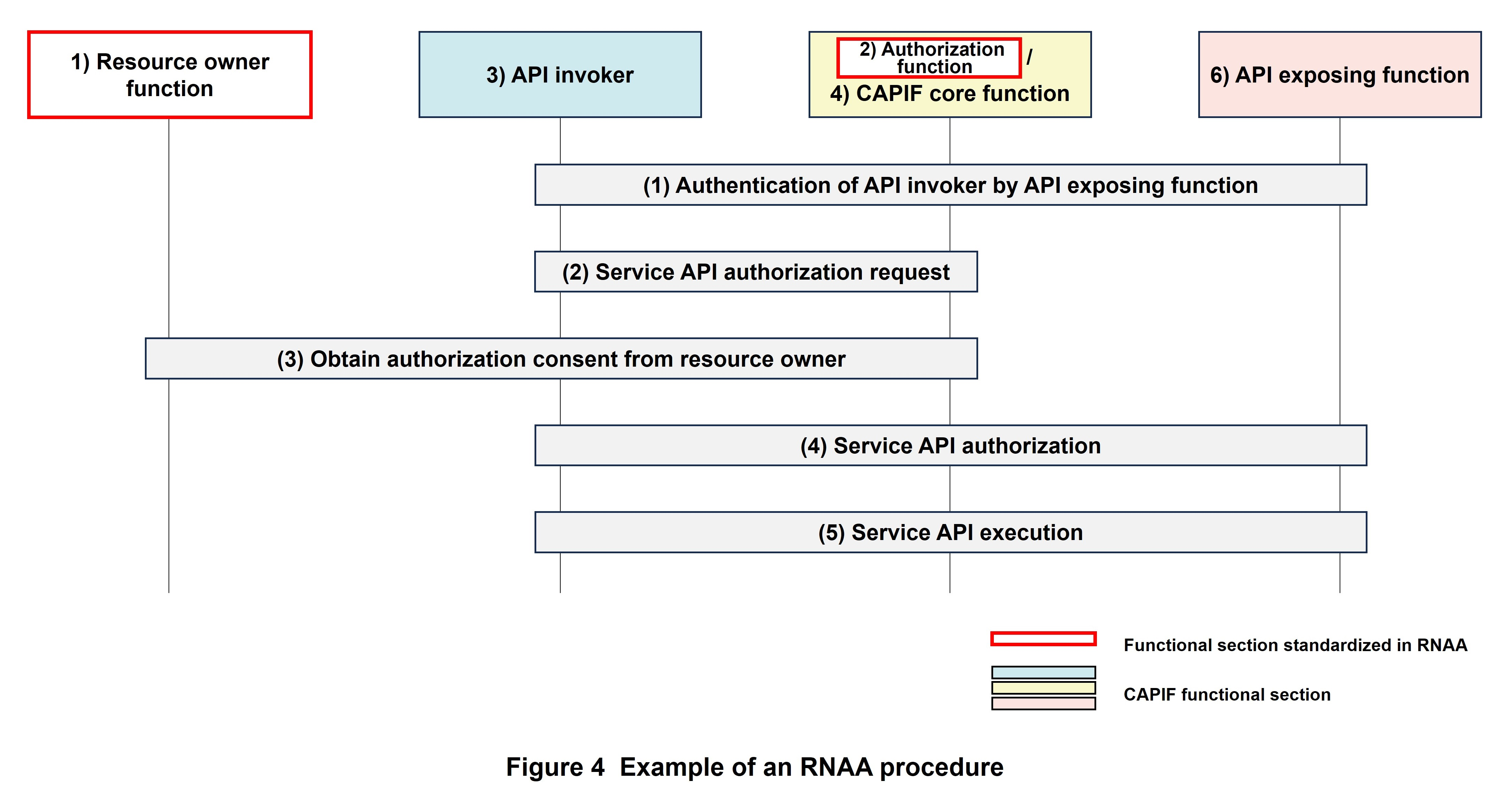
5.4 RNAA Function
Obtaining the consent of the resource owner is an option when an API invoker calls a CAPIF service API. The RNAA function is used in such a case. An example of an RNAA procedure is shown in Figure 4.
The following conditions must be satisfied beforehand as a prerequisite to using RNAA.
- The API invoker must be registered as onboard on the CAPIF side.
- Publishing of the service API has been completed on the CAPIF side and service API is in a discoverable state.
- The API invoker has been authenticated on the CAPIF side.
- A security method for performing authentication and authorization between the API invoker and API exposing function has been decided upon on the CAPIF side (in this article, this is the OAuth token*118-based Transport Layer Security (TLS) *119 method).
- An authorization grant method for use in obtaining the consent of the resource owner when using RNAA has been decided upon on the CAPIF side (in this article, this is the authorization code grant method).
The following explains each step in the procedure shown in Fig. 4.
(1) Authentication of API invoker by API exposing function
The API invoker requests the API exposing function for authentication using the predetermined security method, and the API exposing function authenticates the API invoker after verifying the content of that request.
(2) Service API authorization request
The API invoker sends a service API authorization request to the authorization function within the CAPIF core function.
(3) Obtain authorization consent from resource owner
The authorization function that has received the authorization request authenticates the resource owner and asks the resource owner whether they consent to or do not consent to the authorization request. If the resource owner consents, the authorization function transfers access rights to the API invoker, which then receives an authorization code from the authorization function.
(4) Service API authorization
The API invoker sends the authorization code to the authorization function, which then verifies the API invoker's authentication and authorization code. If no problems are found, the authorization function issues an access token to the API invoker.
(5) Service API execution
The API invoker sends a message requesting execution of the service API with the access token included to the API exposing function. After verifying the content of the message, the API exposing function executes the service API in coordination with the CAPIF core function.
5.5 Future Outlook for RNAA
In Rel-18, the basic architecture and functions of RNAA were specified. From Rel-19 on, the plan is to study RNAA extensions and detailed specifications with the aim of adding functional enhancements, specifications under complex conditions, etc. In addition, NTT DOCOMO, which has been named the SA6 Rapporteur*120 in Rel-19, is now preparing “Guidelines in Using CAPIF” as a technical report targeting parties outside 3GPP to make CAPIF methods including RNAA easier to understand and use. Going forward, NTT DOCOMO will continue to contribute to international standardization activities to expand awareness of RNAA and CAPIF and promote their use in many countries and services.
- SCEF: A logical node for providing some of the functions of a 3GPP system for 4G to parties outside the 3GPP domain.
- TSG SA: A group in 3GPP in charge of drafting technical specifications, namely, specifications related to service requirements, architecture, and security.
- Resource owner: The owner of resources.
- Token: In this article, refers to an access token. It consists of a character string that authorizes access to an API when presented.
- TLS: An encryption protocol in communications.
- Rapporteur: The role of editing specifications, managing work progress and reporting at WG meetings on individual WI and specifications.
-
At 3GPP TSG SA WG5, management functions related to the mobile
Open
At 3GPP TSG SA WG5, management functions related to the mobile communications network are being defined and energetic discussions are being held on intent driven management. Technical specifications (TS28.312 [16]) related to intent driven management were introduced in Rel-17 and extended in Rel-18. The following describes the basic concept, data models, and implementation procedures of intent driven management and discusses the future outlook for this technology.
6.1 Basic Concept
Operation of today's mobile communications network is becoming increasingly complex. It requires that network details be understood and detailed settings be made, all of which increases the burden on the telecommunications operator. In addition, dealing with increasingly diversifying business needs requires that operations adapt to business goals and customer expectations. As a result, it is becoming increasingly important for the telecommunications operator to approach operations from the viewpoint of “what to achieve” rather than “how to achieve it.” Intent driven management is a management technique for driving a system so that a desired state can be provided according to intent that expresses the state to be achieved without having to have detailed knowledge of the network.
Intent specifies expectations in relation to the requirements, targets, constraints, etc. of a specific service or network management workflow. The TS28.312 [16] technical specification describes intent as follows.
- Intent can be understood by humans and can be interpreted by a machine without ambiguity.
- Intent focuses on describing “what” needs to be fulfilled and places little emphasis on “how” to fulfill the results needed. For the intent requester, this reduces the burden of having to know implementation details, and for the intent processer, it provides leeway in investigating alternative options and finding an optimal solution.
- Expectations expressed as intent do not depend on system (platform) implementation, technology, or infrastructure*121.
- Intent needs to be quantifiable from network data so that the state of fulfillment can be measured and evaluated.
1) Intent Classification
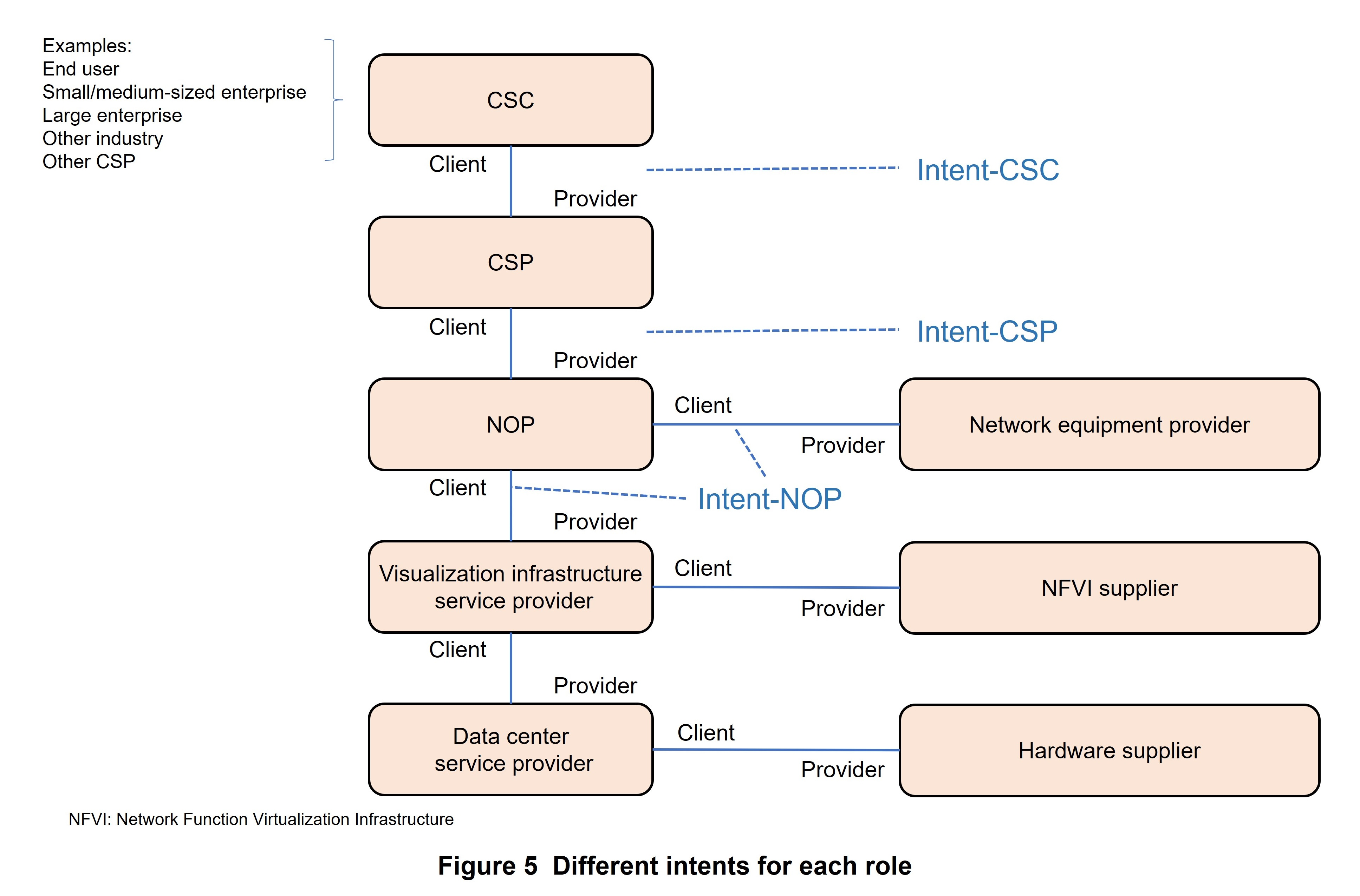
Intent can be classified in the manner shown in Figure 5 (TS28.312 [16]).
- Intent-CSC: Intent from a Communication Service Customer (CSC). By using intent, a CSC can express the features of a communication service to be requested from a Communication Service Provider (CSP) without knowing about detailed management methods in communication services. For example, this request could take the form of “Enable a Vehicle to Everything (V2X) communication*122 service for a group of vehicles within a specific time period.”
- Intent-CSP: Intent from a CSP. By using intent, a CSP can express a request to a network without knowing about detailed network management methods. Such a request could take the form of “Provide a network service that supports V2X communication on National Route 417 and simultaneously supports 500 vehicles.”
- Intent-NOP: Intent from a Network Operator (NOP): By using intent, a NOP itself can express a request with regard to the management and control of a group of network elements (subnetworks, etc.) without knowing about detailed network management methods. This could take the form of “provide a wireless network service that satisfies specified coverage requirements and UE throughput requirements in a specific area.”
2) Intent Numerical Targets
Intent can describe specific numerical targets that differ according to network management needs as summarized below.
- In the case of establishing intent expectation values*123 for deploying network/service-related objects*124, settings could take the form of “Deploy a wireless network in the specified area using the specified frequency, transport, and wireless information (range of Physical Cell ID (PCI)*125, cell ID*126, etc.), network capacity, and performance information.”
- In the case of establishing intent expectation values for network/service-related objects, settings could take the form of “The wireless network in the specified area must satisfy a specific throughput target between RAN and UE.
6.2 Data Models
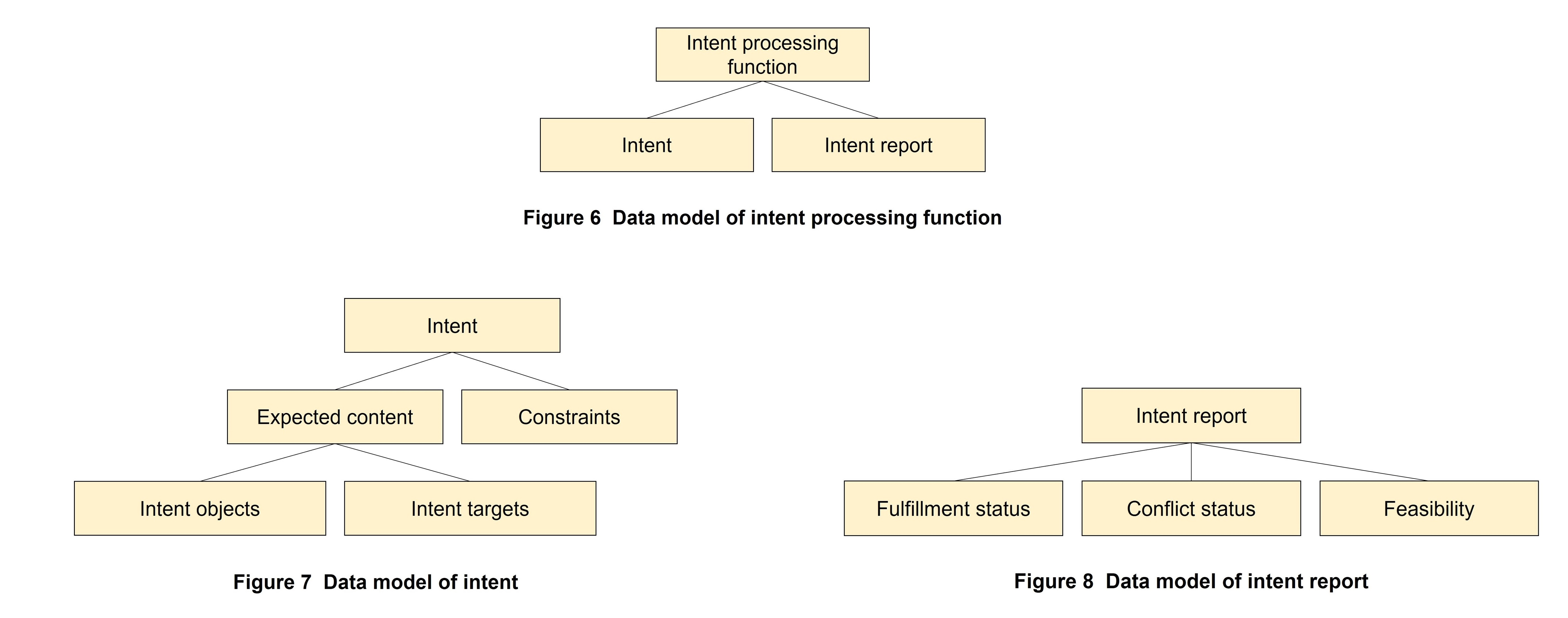
The TS28.312 [16] specification specifies data models. A data model defines the attributes (expected content, priority, etc.) possessed by intent.
As shown in Figure 6 [16], the data model for an intent processing function consists of intent and intent report. This data model is used to manage intent.
As shown in Figure 7 [16], the data model for intent includes expected content and constraints, and expected content, in turn, includes intent objects and intent targets. Here, intent objects indicate objects that apply intent while intent targets indicate specific intent content.
As shown in Figure 8 [16], intent report includes fulfillment status, conflict status, and feasibility.
6.3 Procedures
The TS28.312 [16] specification defines various procedures for exchanging intent between the intent requester and intent processor.
- Create: Procedure for creating intent. The requester can use this procedure to convey the expected content and constraints of the intent.
- Modify: Procedure for modifying intent. The requester can use this procedure to convey a change to the intent.
- Delete: Procedure for deleting intent. The requester can use this procedure to convey deletion of the intent.
- Query: Procedure for obtaining current settings, etc. related to the intent.
- Intent conflict solution: A series of procedures for solving inconsistencies in multiple intents.
- Intent report management: Procedure for reporting intent status. This procedure can be used to convey intent fulfillment status, conflict status, and feasibility.
6.4 Future Outlook
Studies on basic intent functions were completed in Rel-18 and studies on enhanced functions will continue in Rel-19. One example of such an enhancement is a function for conducting arbitration between the intent requester and processor. Such an arbitration function could be used, for example, to convey an alternative when the requested intent is infeasible. This function would be essential to achieving operation of an entire system without human intervention.
In addition, intent is being actively discussed not only at 3GPP but also at other standardization organizations such as the TeleManagement Forum (TM Forum)*127, European Telecommunications Standards Institute Zero Touch Network and Service Management (ETSI ZSM)*128, and ETSI Network Functions Virtualisation (ETSI NFV)*129. In Rel-18, studies progressed through the exchange of information among the standardization organizations concerned, and going forward, there will likewise be a need for exchanging information to ensure consistency.
- Infrastructure: Generic term for physical or virtual data centers, servers, networks, etc. for executing applications.
- V2X communication: V2X is a generic name for wireless communications systems for communication between vehicles and other vehicles (V2V), vehicles and infrastructure such as traffic signals and road signs (V2I), and between vehicles and pedestrians carrying smartphones (V2P).
- Intent expectation values: Numerical goals of the intent.
- Objects: Each object can express an entity or concept existing in the real world so that it can be handled in a software program. An object is expressed as a combination of data that represents the attributes of the target entity and associated operations.
- PCI: Identifier of a physical cell.
- Cell ID: Identifying information given to each cell.
- TM Forum: A non-profit organization that formulates standard specifications for operations in the telecommunications field.
- ETSI ZSM: ETSI is a European telecommunications standardization organization that performs standardization in telecommunications technology. ETSI ZSM is an organization that performs standardization in network operations automation technology.
- ETSI NFV: ETSI is a European telecommunications standardization organization that performs standardization in telecommunications technology. ETSI NFV is an organization that performs standardization in network virtualization infrastructure.
-
This article described enhancements made to 5GC in Rel-18
Open
This article described enhancements made to 5GC in Rel-18 with a focus on enhanced reality and media services, timing services and deterministic communications, network slicing, RNAA, and intent driven management. At present, Rel-19 studies are progressing at 3GPP with the aim of making further enhancements to 5G-Advanced. For its part, NTT DOCOMO will continue to contribute to 5G-Advanced standardization at 3GPP and to the further expansion of mobile communications.
-
REFERENCES
Open
- [1] 3GPP TS26.522 V18.1.0: “5G Real-time Media Transport Protocol Configurations,” Jun. 2024.
- [2] IETF RFC 9331: “The Explicit Congestion Notification (ECN) Protocol for Low Latency, Low Loss, and Scalable Throughput (L4S),” Jan. 2023.
- [3] IEEE Std 1588: “IEEE Standard for a Precision Clock Synchronization Protocol for Networked Measurement and Control Systems,” Edition 2019.
- [4] IEEE Std 802.1AS-2020: “IEEE Standard for Local and Metropolitan Area Networks--Timing and Synchronization for Time-Sensitive Applications.”
- [5] ITU-T G.8265.1: “Precision time protocol telecom profile for frequency synchronization,” Nov. 2022.
- [6] 3GPP TS 29.522 V18.6.1: “5G System; Network Exposure Function Northbound APIs; Stage 3,” Jul. 2024.
- [7] IEEE Std 802.1Q-2022: “IEEE Standard for Local and Metropolitan Area Networks--Bridges and Bridged Networks.”
- [8] IEEE Std P802.1Qdj-d1.3: “IEEE Draft Standard for Local and Metropolitan Area Networks - Bridges and Bridged Networks - Amendment XX: Configuration Enhancements for Time-Sensitive Networking.”
- [9] 3GPP TS23.501 V18.6.0: “System architecture for the 5G System (5GS); Stage 2,” Jun. 2024.
- [10] IEEE Std 802.1CBdb-2017: “IEEE Standard for Local and Metropolitan Area Networks--Frame Replication and Elimination for Reliability.”
- [11] IETF RFC 8655: “Deterministic Networking Architecture,” Oct. 2019.
- [12] IETF RFC 8040: “RESTCONF Protocol,” Jan. 2017.
- [13] IETF RFC 6241: “Network Configuration Protocol (NETCONF),” Jun. 2011.
- [14] 3GPP TS29.565 V18.6.0: “5G System; Time Sensitive Communication and Time Synchronization Function Services; Stage 3,” Jun. 2024.
- [15] GSMA NG.116 V1.0: “Generic Network Slice Template,” May 2019.
- [16] 3GPP TS28.312 V18.4.0: “Management and orchestration; Intent driven management services for mobile networks,” Jun. 2024.

