
Special Articles on 5G Evolution & 6G (2)—Initiatives toward Implementation and Use Cases—
Measurement of Stratospheric Radio Propagation in 38 GHz Band for HAPS Communication System
NTN HAPS Extreme Coverage Extension
Yuki Hokazono, Hinata Kohara, Yuto Muroki, Kenji Fukasawa and Satoshi Nagata
6G Network Innovation Department
Abstract
HAPSs using broadband millimeter waves promise to enable the timely provisioning of the required high-speed large-capacity access in various locations including mountainous areas, air, and sea. Since no radio propagation measurements from the stratosphere to the ground have been conducted in the 38 GHz band, it is necessary to clarify the characteristics of radio propagation to realize the HAPS broadband system. In this article, we report on the world’s first measurement of 38 GHz radio propagation from the lower stratosphere using a high-altitude aircraft, which was conducted in an environment closely similar to real HAPS operations. We present an evaluation of radio propagation characteristics under various elevation angles and weather conditions, as well as the influence of aircraft turning on radio propagation. Experimental results show that it is possible to apply Recommendations of the ITU-R on attenuation values due to weather conditions for terrestrial radio links and satellite communication links to the stratospheric radio propagation environment under the influence of aircraft turning.
01. Introduction
-
One of the key issues in the 5th Generation mobile communications system (5G) Evolution ...
Open

One of the key issues in the 5th Generation mobile communications system (5G) Evolution and 6th Generation mobile communications system (6G) eras is expected to be how to ubiquitously expand the communications area where its benefits can be enjoyed [1]. To achieve this extreme coverage extension*1, we focus on Non-Terrestrial Network (NTN)*2 technology using satellites and High-Altitude Platform Stations (HAPSs)*3. In particular, HAPSs have recently attracted renewed attention for their ability to float in the air at an altitude of about 20 km in fixed locations, which allows them to provide services across terrestrial cells with a radius of approximately 50 km or more [2]. Since their altitude is lower than that of satellites, it is possible to achieve lower latency than satellites in terms of propagation delay. In addition, the 38.0 GHz to 39.5 GHz frequency band was specified for the HAPS system at the 2019 World Radiocommunication Conference (WRC–19)*4 [3]. By using radio waves in the broadband millimeterwave*5 band, a high-speed high-capacity fixed communications system that supports backhaul*66 links at Base Stations (BSs) on 5G networks can be achieved. Thus, HAPSs are considered to be an effective way of deploying services in regions that have suffered natural disasters and in many industrial use cases that have been envisioned for 5G Evolution and 6G.
Although there have been many studies on HAPS communications around the world, there have been no measurements of radio propagation in the 38 GHz band from the stratosphere assuming HAPS. A study that proposed link budgets when using HAPS for backhaul communications has been validated through emulation considering millimeterwave bands [4], but no demonstration experiment has been carried out and the attenuation due to weather conditions has not been analyzed in detail. Another study measured the 60 GHz band using Unmanned Aerial Vehicles (UAVs) such as drones [5], but their flight altitude and flight pattern were different from those of HAPSs; thus, it cannot be used for the evaluation assuming the propagation between HAPS and the ground. Other studies performed airborne radio propagation measurements assuming HAPSs [6][7], but these measurements were taken either in low frequency bands below 6 GHz or at altitudes as low as 3 km and with delays shorter than those that occur in a stratospheric HAPS system.
In our 39 GHz band radio propagation measurement conducted in February 2021 from an altitude of approximately 3 km above the ground [8], we confirmed a significant increase in propagation loss*7 due to fluctuations in the directivity gain of transmitter and receiver antennas caused by aircraft turning and the shielding of the aircraft itself. This indicates that it is important to use control technology to suppress the effects of aircraft turning while maintaining a constant received power. Because of the limitations of the small aircraft used in this experiment, it was not possible to conduct measurements in a rainy environment, and therefore measurements in inclement weather will be required separately.
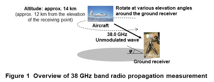
In October 2022, we conducted the world’s first measurement of 38 GHz band radio wave propagation from a transmitter in the lower stratosphere to a receiver on the ground in order to realize a communication area from the sky for HAPS for broadband use. In this experiment, as shown in Figure 1, a high-altitude aircraft equipped with a transmitter flew in the lower stratosphere, and radio waves in the 38 GHz band were transmitted from the transmitter, and radio propagation characteristics*8 were measured at multiple elevation angles using a receiver on the ground. In addition, taking into account that radio waves in the 38 GHz band are susceptible to attenuation due to rainfall, measurements were made under clear sky, cloudy, and rainy weather conditions. To address the issues raised in the aforementioned experiment from about 3 km above the ground [8], namely, propagation loss due to aircraft turning and shielding by the aircraft itself, a mechanical tracking function was installed in the ground receiving parabolic antenna, and the transmitting horn antenna on the aircraft was placed outside of the bottom of the aircraft.
This article describes the measurement of 38 GHz band radio propagation from the lower stratosphere using a highaltitude aircraft. Specifically, we will refer to Recommendations of the International Telecommunication Union Radiocommunication Sector (ITU-R)*9 compiled by ITU-R for terrestrial radio and satellite communication links, especially those that address attenuation values due to weather conditions, and confirm if those Recommendations are also applicable to the stratospheric radio propagation environment under the influence of aircraft turning.
This work was supported by the funding from the Ministry of Internal Affairs and Communications (Research and Development for Expansion of Radio Resources; JPJ000254).
- Extreme coverage extension: Extending the area in which base stations can communicate with mobile terminals to any location, including the air, sea and space, that is not covered by the current mobile communication system.
- NTN: A network that extends the communications area to diverse locations including the air, sea, and space using non-terrestrial media such as satellites and high-altitude platform stations without limiting the coverage area to land.
- HAPS: An airborne platform that is designed to operate in the stratosphere on board a vehicle such as a solar-powered aircraft or airship.
- WRC-19: A conference that reviews, and if necessary, revises Radio Regulations, the international treaty governing the use of radio-frequency spectrum, and the orbits of geostationary and non-geostationary satellites. The conference normally meets once every three to four years, and is attended by administrations, ITU registered corporations and related organizations.
- Millimeter wave: Radio signals in the frequency band from 30 GHz to 300 GHz as well as the 28 GHz band targeted by 5G that are customarily called “millimeter waves.”
- Backhaul: In a mobile communication network, a backhaul is a fixed line that supports high-speed, high-capacity transmission of information between a large number of wireless base stations and the core network.
- Propagation loss: The amount of attenuation in the power of the signal emitted from the transmitting station till it arrives at the reception point.
- Radio propagation characteristics: Refers to characteristics such as propagation loss in a demonstration environment.
- ITU-R: The radiocommunication sector of the ITU, which is an international organization in the telecommunications field. It conducts studies required to revise international regulations for radio communications and conducts research on radio communications technology and operation.
-
Since radio waves in the 38 GHz band are susceptible to attenuation due to rainfall, ...
Open
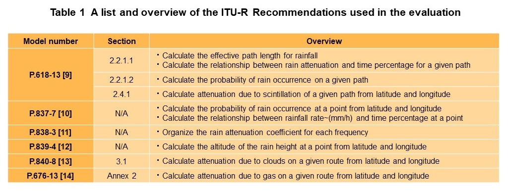
Since radio waves in the 38 GHz band are susceptible to attenuation due to rainfall, accurate estimation of the rainfall attenuation probability is necessary to evaluate the availability of the HAPS system. Many methods for estimating rainfall attenuation probability have been proposed for terrestrial radio and satellite communication links, and they are summarized mainly in the ITU-R Recommendations [9]– [12].
It is significant to confirm whether the rainfall attenuation estimation method of the ITU-R Recommendation can be used in the propagation environment of the HAPS system as well as in satellite communication links. In this experiment, radio propagation measurements in the 38 GHz band are performed under various weather conditions at various possible elevation angles, and analyzed according to the ITUR rainfall attenuation estimation model. In addition to rainfall attenuation, cloud, gas, and scintillation*10 attenuation are also summarized in the ITU-R Recommendations [9][13][14], and we will confirm through this experiment whether these Recommendations are equally applicable to the propagation environment of the HAPS system. A list and overview of the ITU-R Recommendations used in the evaluation is given in Table 1.
In the ITU-R Recommendation for satellite communication links, if the latitude, longitude, propagation path length and elevation angle are known, it is possible to calculate the relationship between the attenuation due to rainfall, clouds, gas and scintillation in various frequency bands and time probability in the propagation path. For example, if the atmospheric attenuation of a given path is calculated to be x dB at an annual time probability of 1 %, it means that the attenuation is greater than x dB for 1 % of the time during the year and less than x dB for the remaining 99 % of the time. These time probabilities can be derived on a monthly or yearly basis. Additionally, if the distribution of rainfall rate along the radio propagation path is known, the rainfall attenuation along the propagation path can be determined with high accuracy.
- Scintillation: A phenomenon whereby amplitude, phase, and polarization undergo short-period fluctuations when radio waves pass through the atmosphere in radio propagation.
-
Since radio waves in the 38 GHz band are susceptible to attenuation due to rainfall, ...
Open
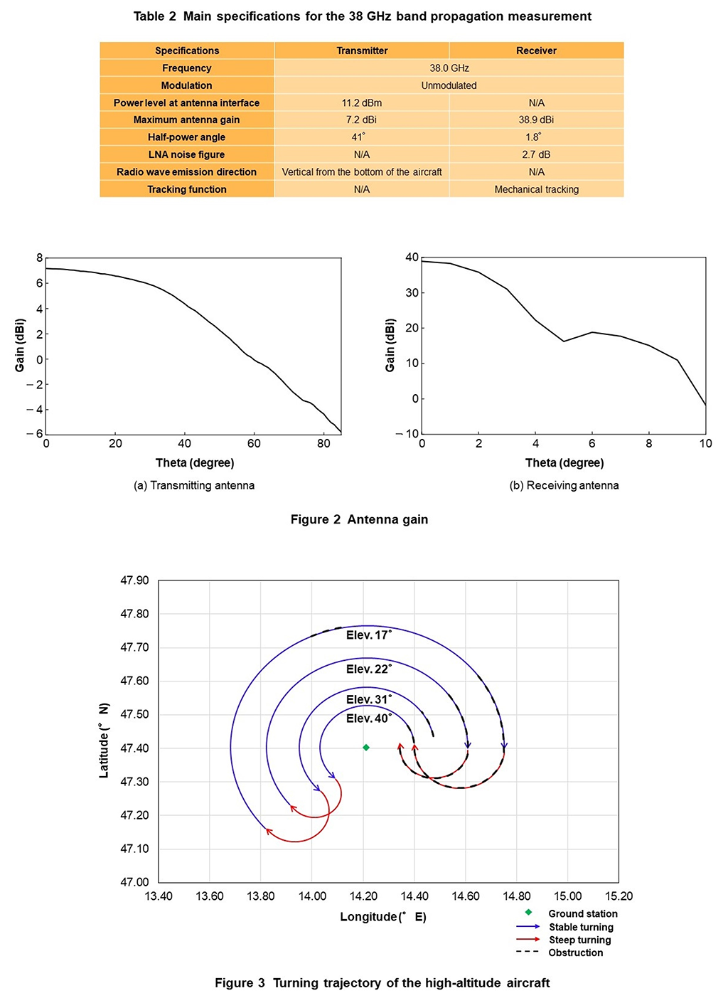
An overview of the 38 GHz radio propagation measurements using a high-altitude aircraft is shown in Fig. 1. The measurements were performed on October 12, 2022, at Planneralm in central Austria, in an environment where the free-space path loss could be measured. A transmitting horn antenna was mounted on the bottom of an aircraft flying at an altitude of about 14 km in the lower stratosphere at a maximum airspeed of about 400 km/h. The aircraft transmitted an unmodulated signal at 38 GHz. The signal is received by the ground antenna, and the received power is measured by a spectrum analyzer*11 after passing through an attenuator*12 and a Low-Noise Amplifier (LNA)*13. The altitude of the ground receiving point is about 2 km, and therefore the vertical distance from the aircraft is about 12 km.
Table 2 gives the main specifications of the experimental equipment, and Figure 2 shows their antenna gains*14. The transmitter antennas are installed so that they are exposed outside the bottom of the aircraft to minimize the effect of the aircraft shielding. To ensure that the transmitter operates in a stratospheric environment, the transmitter characteristics were measured by simulating a stratospheric environment through vibration tests, temperature tests, and pressure tests in a vacuum environment. On the other hand, the receiving antenna has a tracking function to maintain constant receiving power while minimizing the effects of aircraft turning. The tracking method is a mechanical tracking that controls the azimuth and elevation angles using real-time Global Positioning System (GPS) data from the aircraft, which is sufficient for the maximum angular velocity*15 of the aircraft relative to the ground station. Other losses including cable loss and filter loss of the transmitter and receiver were measured in advance and used to evaluate the received power.
Figure 3 shows the turning trajectory of the high-altitude aircraft used to measure radio propagation at multiple elevation angles. To investigate the effect of weather changes on the propagation of radio waves, two flights were made on the same trajectory at different times. The blue curves in Fig. 3 show stable turnings in which the elevation angle of the transmitting and receiving points is constant between each trajectory, which is a concentric circle around the receiving antenna. The red curves show steep turnings from one elevation angle to another. The black dotted lines are the sections where obstacles such as trucks existed between the transmitter and receiver points, which are excluded from the evaluation. The black dotted line drawn between 14.00 and 14.20 °E had obstructions only on the second flight.
The measurements were conducted on selected days when clear sky, cloudy, and rainy weather conditions appeared, and the attenuation due to rainfall, clouds, atmosphere, and scintillation was evaluated in addition to the free-space path loss. According to the okta data, the hourly cloud cover on the day of the first flight was 7 oktas*16 with light rain and mostly cloudy weather, while it was 6 oktas on the day of the second flight with mostly cloudy weather. At least on the second flight, there was a clear period of time with no clouds in the propagation path.
Furthermore, to evaluate the effect of sudden fluctuations in aircraft’s attitude caused by turning on radio propagation, we will also evaluate the received power for the stable and steep turning trajectories shown in Fig. 3, focusing on the variation of the received power from the expected value for each trajectory.
- Spectrum analyzer: A measuring device that displays and analyzes the distribution of frequency components (spectrum) included in a signal.
- Attenuator: A device that can drop the input signal to a suitable signal level.
- LNA: Equipment which is used to amplify a signal directly after it is received by the antenna. Very little noise is added to the signal in amplification, so even very weak signals can be amplified with little distortion.
- Antenna gain: A measure of the sharpness of antenna directivity usually expressed as the ratio of radiated power to that of an isotropic antenna.
- Angular velocity: The velocity of an object rotating about a center point expressed in angular terms.
- Oktas: In aviation weather observations, a unit of cloud cover when looking up divided into 9 levels. 0 octas indicates clear sky with no clouds while 8 octas indicates a sky completely covered by clouds.
-
Here, we present an evaluation of radio propagation in the 38 GHz band measured ...
Open
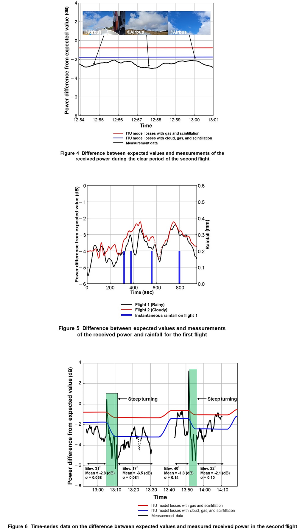
Here, we present an evaluation of radio propagation in the 38 GHz band measured from the lower stratosphere. This evaluation uses the measurement parameters described above. Figures 4, 5, and 6, which are drawn using moving averages of 10 points (about 20 seconds) of data to make the time-series data easy to read.
4.1 Tracking Accuracy Evaluation of Receiving Antenna
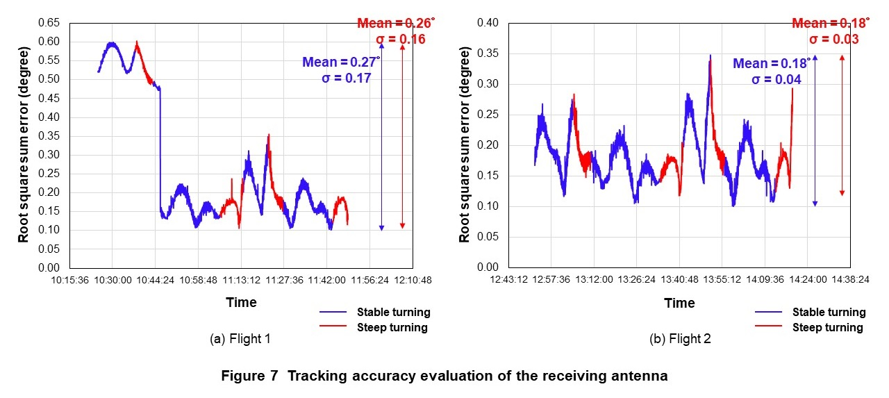
Figure 7 shows the tracking accuracy of the receiving antenna measured over two flights on the turning trajectory shown in Fig. 3. The Root Square Sum (RSS) error*17 of the tracking angle was calculated considering the azimuth and elevation angle errors and a general GPS estimation error of 5 m. In Fig. 7(a), the RSS error is relatively large from the start of the measurement to 10:46:01, but this is due to a tracking error in the elevation angle. The calibration*18 is instantly corrected for this error at 10:46:01, and thereafter the tracking accuracy remains stable. In addition, in Fig. 7(b), the RSS error in the second flight is within a maximum of 0.35°, and the calculated variation in the transmitter and receiver antenna gains is within 1 dBi. Furthermore, there is almost no difference in the mean and standard deviation*19 of the RSS error for the stable and steep trajectories overall, which confirms that the tracking accuracy of the receiving antenna is sufficiently high.
4.2 Evaluation in Various Weather
First, we evaluate the difference from the ideal freespace path loss considering the antenna gain and propagation distance of the transmitter and receiver in clear weather by using the data from the second flight. As shown in Fig. 4, at 13:00:01 of the second flight, the propagation path between the transmitter and receiver points becomes clear at that moment, and the received power is higher than that in the preceding and following time periods. At this time, the elevation angle between the transmitting and receiving points was 31°, and the difference from the ideal free-space path loss was about -2.0 dB.
Possible differences from the ideal free-space path loss include gas loss, scintillation loss, gain loss due to tracking errors, and an increase in the loss of the transmitter and receiver equipment from the prior measurements. Attenuation of the gas and scintillation at an elevation angle of 31°in October at the experiment location was calculated using ITU-R recommendations P.618 [9] and P.676 [14], and the attenuation at a time percentage of 1 % was found to be about 0.7 dB and 0.1 dB respectively. The red line in Fig. 4 is the sum of these attenuations, 0.8 dB, subtracted from the reference 0 dB. As for the gain loss due to tracking error, the RSS error of the tracking angle at 13:00:01 is found to be 0.18°from Fig. 7(b), from which we calculate the combined transmit and receive antenna gain variation to be at most 0.5 dB. We also confirmed that the LNA gain of the receiver was thermally degraded for the second flight, resulting in a loss of 1.0 dB. The total of the above losses is 2.3 dB, and the error from 2.0 dB measured as the loss from the free space path loss is as small as 0.3 dB. This suggests that the gas and scintillation loss calculations in ITU-R Recommendations P.618 [9] and P.676 [14] are applicable to the propagation environment of the HAPS system as well as the satellite system. Speaking of the blue line in Fig. 4, it is the line obtained from ITU-R Recommendation P.840 [13] for cloud attenuation at the local October time percentage of 10 % and subtracted from the reference 0 dB in addition to attenuation due to gas and scintillation.
Next, we compare the received power in rainy and cloudy weather for two flights flown on the same circular trajectory exactly at the same location at an elevation angle of 17° Fig. 5 shows the difference from the expected values of the received power and the instantaneous rainfall per minute for each flight. The reference time of 10:46:40 of the first flight and 13:13:24 of the second flight are set to 0 second in Fig. 5. The weather conditions at the time of the measurements were light rain and mostly cloudy with cloud cover around 7 oktas for the first flight, and mostly cloudy with cloud cover around 6 oktas for the second flight. Fig. 5 plots the data collected during the time of stable flight on the same trajectory. Rainfall amounts plotted are those observed on the first flight by the rain gauge installed at the receiving station. The expected values are derived from the ideal freespace path loss considering the antenna gain and propagation distance of the transmitter and receiver. The second flight, from 576 to 665 seconds, shown by the dashed line in Fig. 5, is excluded from the evaluation because during this time period, there was a reduction in the received power due to the presence of obstacles blocking the propagation path. Note that there is a 1.0 dB loss due to the thermal degradation*20 of the receiver’s LNA gain in the second flight only, and this loss is corrected for the comparison of the received power in rainy and cloudy weather.
Fig. 5 shows the difference between the expected values and the measured values during the second flight in cloudy weather, which varies from 1.2 dB to 3.5 dB as a result of correction for thermal degradation of the LNA. The main components of this difference are assumed to be gas loss, scintillation loss, and gain loss due to tracking error, as in the clear sky evaluation, plus loss due to clouds. Then, each of these losses is evaluated using the ITU-R Recommendations.
From ITU-R Recommendations P.618 [9] and P.676 [14], the attenuation of the gas and scintillation at a monthly time percentage of 1 % is calculated to be about 1.2 dB and 0.1 dB, respectively. Next, for the attenuation due to clouds, we estimate that the cloud covers of about 6 to 7 oktas observed on the day of the measurement corresponds to an occurrence rate of 10 to 40 % of the time percentage in October and calculate the attenuation from ITU-R Recommendation P.840 [13] to be about 0.2 to 1.9 dB. The gain loss due to the tracking error is at most 0.5 dB, as in the clear sky evaluation. The total of the above losses is 2.0 to 3.7 dB, and the error from the measured losses is as small as 0.8 dB. This suggests that the cloud attenuation calculation based on ITU-R Recommendation P.840 [13] is applicable to the propagation environment of the HAPS system as in the satellite system.
Next, after correction for the 1.0 dB thermal degradation of the LNA in the second flight from Fig. 5, the analysis showed that the received power difference between the rainy and cloudy flights averaged 1.4 dB. On the other hand, for the one-hour rainfall total of 0.8 mm measured in the first flight, the rainfall attenuation in the measurement path was calculated to be approximately 1.6 dB, using the ITU Recommendations [9]–[12] related to rainfall. The error of 0.2 dB, which is a small difference from the measured received power difference of 1.4 dB between rainy and cloudy flights, suggests that the rainfall attenuation calculation using the rainfall-related ITU Recommendations [9]–[12] can be applied to the propagation environment of the HAPS system in the same way as for the satellite system.
4.3 Evaluation at Various Elevation Angles
To compare the received power measured at various elevation angles, we examine the time series data shown in Fig. 6 on the difference between the expected values and the received power measured during the second flight under cloudy skies of around 6 oktas. The expected values are derived from the ideal free-space path loss considering the antenna gain and propagation distance of the transmitter and receiver. As in Fig. 4, the attenuation due to the gas and scintillation at the local October time rate of 1 % is subtracted from the reference 0 dB shown as the red line, and the attenuation due to clouds at the local October time rate of 10 % is added to these attenuations and subtracted from the reference 0 dB as the blue line. Note that the 1.0 dB thermal degradation of the LNA in the second flight was not corrected. The dashed line in Fig. 6 indicates the time period when the received power was reduced due to the presence of obstacles blocking the propagation path, and this coincides with the time period for which data is missing.
The mean and standard deviation of the difference between the expected values and measured values of received power at each elevation angle were calculated, except for the time period when obstructions were present and during steep turning. The mean value was -2.8 dB with a standard deviation of 0.058 at an elevation angle of 31°, -3.5 dB with a standard deviation of 0.081 at an elevation angle of 17°, -1.8 dB with a standard deviation of 0.14 at an elevation angle of 40°, and 2.1 dB with a standard deviation of 0.10 at an elevation angle of 22°. In particular, during the time period at the lowest elevation angle of 17°, the difference between the expected values and measurements of received power tended to be larger because of the increase in loss due to clouds, gas, and scintillation due to the longer propagation path.
4.4 Evaluation of Aircraft Turning Impact
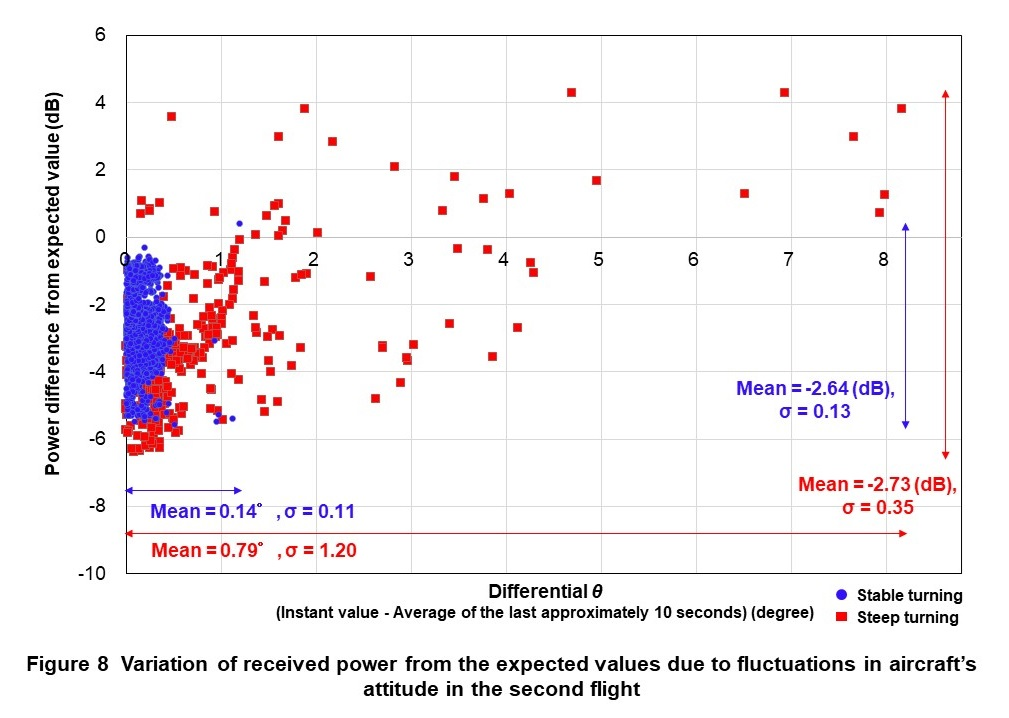
To evaluate the effect of fluctuations in aircraft’s attitude on radio propagation, we focus on the variation of the received power from the expected values for the stable and steep turn trajectories shown in Fig. 3. The expected values are derived from the ideal free-space path loss that takes into account the antenna gain and propagation distance of the transmitter and receiver. The variation of the angle θ between the straight line connecting the bottom of the aircraft and the transmitter/receiver points is used as a parameter that indicates the fluctuations in aircraft’s attitude. As the variation of θ, we focus on the difference value obtained by subtracting the average value of θ during the last 10 seconds from the instantaneous value of θ to suppress errors in the measurement time interval.
Figure 8 shows the calculated variation of the received power from the expected values for each of these θ difference values during the second flight in cloudy weather. The mean value of the θ difference is 0.79°with a standard deviation of 1.20 for the steep turning, which is more variable than the mean value of 0.14°and the standard deviation value of 0.11 for the stable turning. Similarly, the mean value of the received power difference from the expected values is -2.73 dB with a standard deviation of 0.35 for the steep turning, which is more variable than the mean value of -2.64 dB and the standard deviation value of 0.13 for the stable turning.
The experimental results confirm the importance of considering the effects of such turns on the received power in link budget for the future practical application of HAPS. The first factor that caused the received power to deviate from the theoretical value during aircraft turns in this evaluation is the unexpected variation in the gain of the transmitter antenna due to the structure of the aircraft. Although the transmitting antenna was directed outward from the bottom of the aircraft, it was presumably affected by the structure of the aircraft when the aircraft tilted significantly. The second factor is the dvariation in the thickness of the cloud cover. During the measurement period, the cloud cover was about 6 oktas, but its thickness varied from one place to another, which caused the attenuation to vary by several dB.
- RSS error: Given multiple values indicating error between measured and true values, the value obtained by squaring each of those values, summing those squares, and taking the square root of that sum. In this article, we use RSS to group together and evaluate tracking-angle error in the vertical and horizontal directions.
- Calibration: Pre-correction of imbalance in characteristics among antennas when arranging multiple antenna elements, etc. to emit signals in a suitable manner.
- Deviation: Dispersion or fluctuation from standard values.
- Thermal degradation: Mechanical degradation in an electrical component or module consisting of multiple elements having different thermal expansion coefficients at the time of repeated expansion and contraction caused by temperature changes.
-
This article reports on the world’s first measurement of radio propagation ...
Open
This article reports on the world’s first measurement of radio propagation in the 38 GHz band from the lower stratosphere using a high-altitude aircraft, which was conducted in an environment closely similar to real HAPS operations. We evaluated the propagation characteristics of radio waves under various elevation angles and weather conditions as well as the effect of fluctuations in aircraft’s attitude caused by turning of the aircraft on the propagation of radio waves. The evaluation showed that it is possible to apply the ITU-R Recommendations [9]–[14] on attenuation of satellite communication links under various weather conditions to the stratospheric radio propagation environment. It also highlighted the importance of studying the link budget considering the effect of aircraft turning on the received power for the future practical application of HAPS.
On the other hand, the flight speeds used in this experiment could have been faster than those of actual HAPS aircraft because the high-altitude aircraft used in this experiment flew at a maximum airspeed of approximately 400 km/h. As future work, we plan to quantitatively compare the fluctuations in aircraft’s attitude of real HAPS aircraft with that of this measurement and to study the link budget of a practical system. In addition, we plan to construct a highly accurate rainfall attenuation estimation model for HAPS links in the 38 GHz band through measurement of radio propagation at various rainfall intensities at various possible positions of HAPS and ground stations.
-
REFERENCES
Open
- [1] NTT DOCOMO, INC.: “White paper: 5G Evolution and 6G (version 5.0),” Jan. 2023.
- [2] HAPS Alliance homepage.
 https://hapsalliance.org/
 - [3] ITU: “World Radiocommunication Conference 2019 (WRC–19) Final Acts,” ITU Publications, pp. 41–43, 2020.
- [4] A. Nauman and M. Maqsood: “System design and performance evaluation of high altitude platform: Link budget and power budget,” Proc. of the 2017 19th International Conference on Advanced Communication Technology, pp. 138–142, Feb. 2017.
- [5] S. G. Sanchez, S. Mohanti, D. Jaisinghani and K. R. Chowdhury: “Millimeter-wave base stations in the sky: An experimental study of UAV-to-ground communications,” IEEE Transactions on Mobile Computing, Vol. 21, No. 2, pp. 644–662, Feb. 2022.
- [6] H. Omote, A. Sato, S. Kimura, S. Tanaka, H. Y. Lin and T. Yamazato: “Clutter loss characteristics at the line-of-sight and non-line-of-sight boundaries in high base station environments,” Proc. of the 2023 17th European Conference on Antennas and Propagation, pp. 1–4, Mar. 2023.
- [7] NTT DOCOMO, INC. and Airbus Defence and Space Limited press release: “Zephyr High Altitude Platform Station (HAPS) achieves connectivity in trial conducted by Airbus and NTT DOCOMO,” Nov. 2021.
- [8] Y. Hokazono, Y. Kishiyama, T. Asai, T. Takamori, J. Suzuki and H. Kitanozono: “Experimental 39-GHz band propagation measurements for coverage extension from the sky,” Proc. of the 2022 16th European Conference on Antennas and Propagation, pp. 1–5, Mar. 2022.
- [9] ITU-R Recommendation P.618-13: “Propagation data and prediction methods required for the design of Earth-space telecommunication systems,” Dec. 2017.
- [10] ITU-R Recommendation P.837-7: “Characteristics of precipitation for propagation modelling,” Jun. 2017.
- [11] ITU-R Recommendation P.838-3: “Specific attenuation model for rain for use in prediction methods,” Mar. 2005.
- [12] ITU-R Recommendation P.839-4: “Rain height model for prediction methods,” Sep. 2013.
- [13] ITU-R Recommendation P.840-8: “Attenuation due to clouds and fog,” Aug. 2019.
- [14] ITU-R Recommendation P.676-13: “Attenuation by atmospheric gases and related effects,” Aug. 2022.

