
Special Articles on 5G SA
Radio Base Station Equipment for 5G SA Systems
5G 5G SA Radio Base Station Equipment
Keisuke Saito, Rei Nagashima and Yuya Hoshizaki
Radio Access Network Development Department
Nobukazu Uno
R&D Strategy Department
Abstract
NTT DOCOMO launched 5G commercial services based on NSA in March 2020, and further launched commercial services based on 5G SA in December 2021, which combines 5GC, a core network facility dedicated to 5G, and 5G radio base stations. This article describes the details of the 5G radio base station equipment developed to provide 5G SA commercial services.
01. Introduction
-
In March 2020, NTT DOCOMO started providing 5G commercial services ...
Open

In March 2020, NTT DOCOMO started providing 5G commercial services based on Non-Stand Alone (NSA)*1, which links 4G/5G radio equipment with 4G core network*2 equipment. 5G NSA supports high-speed, high-capacity services, one of the features of the 5G system, mainly in areas of high demand. In December 2021, NTT DOCOMO began offering commercial services based on 5G SA*3 to provide network services that support high reliability, low latency, and simultaneous connection of several pieces of UE as well as high speed and high capacity. Through the 5G SA deployment, we will create new industries, such as those providing flexible application-aware services through network slicing*4 and low-latency services through Mobile Edge Computing (MEC)*5.
This article describes the system configuration of 5G SA, functions that contribute to high speed and high capacity, call processing control functions, and access control functions to achieve safety and security.
- NSA: A form of connection to a 5G radio access network that is designed to be used in conjunction with LTE (enhanced LTE (eLTE)).
- Core network: A network consisting of switching equipment and subscriber-information management equipment. UE communicates with the core network via the radio access network.
- SA: A form of mobile communications network on which UE connects using a single radio technology.
- Network slicing: One format for achieving next-generation networks in the 5G era. Architecture that optimally divides the core network in units of services corresponding to use cases, business models, etc.
- MEC: A mechanism to deploy servers and storage closer to the user on mobile communications network. Low latency enables the provision of highly real-time services.
-
This chapter describes the configuration of the Radio Access Network ...
Open
This chapter describes the configuration of the Radio Access Network (RAN)*6 system that enables 5G services.
2.1 NSA System Configuration
The 5G commercial services launched by NTT DOCOMO in March 2020 are based on NSA. In the NSA system, 5G services are provided using the evolved NodeB (eNB)*7 equipment as an anchor*8 instead of using the next generation NodeB (gNB)*9 equipment alone. As shown in Figure 1, in NSA operations, the eNB is connected to the gNB providing New Radio (NR)*10 using the X2*11 interface, and the eNB and gNB are connected to the Evolved Packet Core (EPC)*12 using S1*13 interfaces. For a technical overview of NSA, see reference [1].
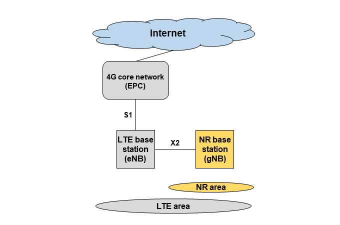
Figure 1 NSA system
2.2 SA System Configuration
From December 2021, NTT DOCOMO launched commercial 5G SA services for enterprise customer users, and then added features such as higher speed and voice support for consumer users in August 2022. NTT DOCOMO has adopted a network configuration (Option 2 architecture) in which services are provided using only the gNB radio equipment and a core network (5G Core network (5GC)*14) dedicated to 5G SA. For a technical overview of network architecture such as Option 2, see reference [1].
As shown in Figure 2, in the SA system, the gNB - gNB connection is made using the Xn*15 interface, while the gNB - 5GC connection is made using the NG*16 interface.
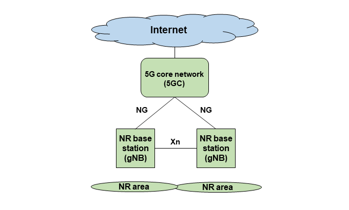
Figure 2 SA system
The configuration diagrams of the NSA and SA systems are shown separately in Figs. 1 and 2 for convenience, but in actual DOCOMO commercial operations, both the NSA and SA systems are operated with a single piece of gNB equipment. The 5G network configuration based on actual operation is shown in Figure 3. To support the SA function in gNB equipment, no new hardware installation is required, and only a software update is needed.
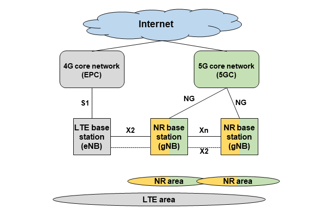
Figure 3 5G network operation (NSA/SA)
- RAN: A network consisting of base stations that control the radio layer, etc., located between the core network and UE.
- eNB: A radio base station that supports the LTE radio system.
- Anchor: A logical node site for control-signal or user-bearer switching.
- gNB: A radio base station that supports the 5G radio system.
- NR: The radio interface between base stations (gNB) and User Equipment (UE) specified in 3GPP Release 15.
- X2: A reference point between eNB, defined by 3GPP.
- EPC: The fourth-generation IP-based core network specified by 3GPP for LTE and other access technologies.
- S1: The interface between EPC and eNB.
- 5GC: The core network specified by 3GPP for fifth-generation mobile telecommunications systems.
- Xn: The interface between gNBs.
- NG: The interface between 5GC and gNB.
-
With the launch of the commercial 5G SA service for smartphones, ...
Open
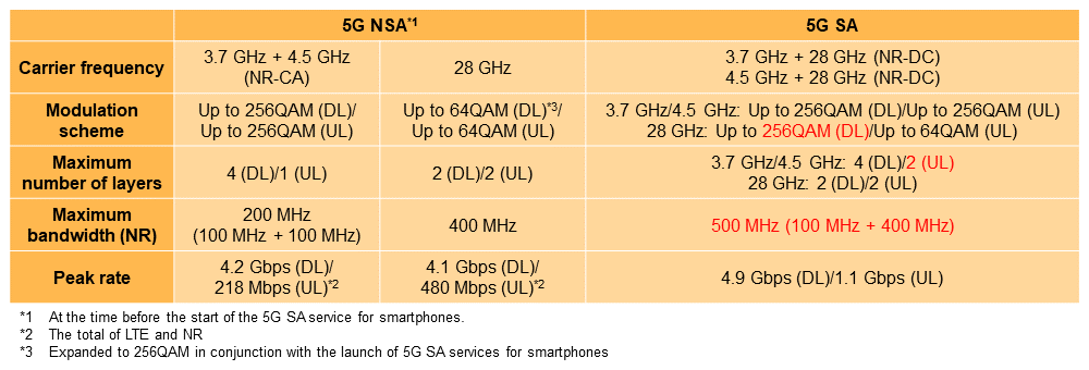
With the launch of the commercial 5G SA service for smartphones, NTT DOCOMO has achieved higher speeds and capacities by introducing functions that contribute to high speed and high capacity together (Table 1). The following describes the three main functions implemented. In the future, we will focus more on the expansion of SA than NSA, and will develop and implement high-speed, high-capacity functions in a timely manner to quickly upgrade mobile networks and improve the customer experience.
Table 1 NSA/SA service specifications
3.1 Aggregation of 3.7 GHz/4.5 GHz and 28 GHz (Support for NR-DC)
For 5G NSA services, LTE and NR frequencies are combined through Dual Connectivity (DC)*17, called EUTRA-New Radio DC (EN-DC)*18, to achieve higher speed and capacity than LTE/LTE-Advanced*19. This enables combination of 3.7 GHz and 4.5 GHz to provide a maximum downlink speed of 4.2 Gbps and use of 28 GHz to provide a maximum uplink speed of 480 Mbps (sum of LTE and NR) (as of the time before the launch of the 5G SA service for smartphones). As a world first, when launching 5G SA services for smartphones in August 2022, NTT DOCOMO implemented NR-DC*20 in the commercial network to enable simultaneous communications by combining 3.7 GHz or 4.5 GHz with 28 GHz, thereby providing high-speed, large-capacity communications in SA services (Figure 4).
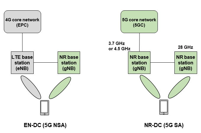
Figure 4 EN-DC and NR-DC
In addition to DC, Carrier Aggregation (CA)*21 is another technology that achieves wide bandwidth by combining multiple frequencies and has been also introduced as a method of speeding up LTE/LTE-Advanced and 5G NSA (Down Link (DL) CA in 3.7 GHz and 4.5 GHz). On the other hand, 3.7 GHz/4.5 GHz and 28 GHz have different subcarrier spacing*22 and slot*23 lengths due to different radio propagation characteristics, and are not highly compatible with CA, which requires more closely coordinated control between frequencies. Considering these points, NTT DOCOMO reached the conclusion to introduce DC. The introduction of NR-DC enabled broadband communications up to 500 MHz bandwidth, combining 100 MHz bandwidth in 3.7 GHz and 4.5 GHz and 400 MHz in 28 GHz to improve peak rates and increase capacity.
3.2 Expansion of Uplink MIMO (2×2 UL MIMO)
For Physical Uplink Shared CHannel (PUSCH)*24 used for uplink communications, the number of layers in 3.7 GHz and 4.5 GHz in the NSA network was 1 layer at maximum (LTE: 1 layer, NR (3.7 GHz and 4.5 GHz): 1 layer). The SA network will newly introduce 2 × 2 UL Multiple Input Multiple Output (MIMO)*25 with up to two layers in 3.7 GHz and 4.5 GHz to increase the uplink speed (Figure 5).
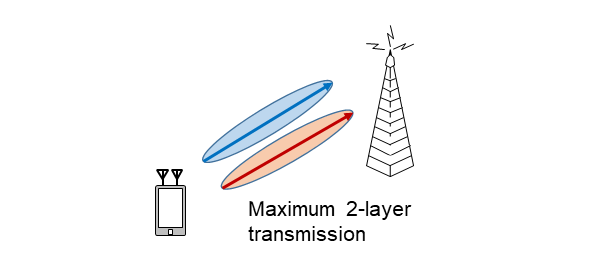
Figure 5 UL MIMO
The introduction of this functionality will double the peak throughput of uplink communications in 3.7 GHz and 4.5 GHz and improve frequency utilization efficiency*26. As needs have been increasing in recent years, faster uplink communications are expected to improve the user experience of uplink communications, such as video uploading.
3.3 Extension of Downlink Modulation Scheme (256QAM)
In 28 GHz, the modulation scheme of Physical Downlink Shared CHannel (PDSCH)*27 used for downlink communications has been maximum 64 Quadrature Amplitude Modulation (QAM)*28. In response to the new performance specification regarding downlink 256QAM in 28 GHz in the 3GPP Release16 specification, NTT DOCOMO introduced this modulation scheme in conjunction with the deployment of the 5G SA system.
The application of 256QAM makes it possible to transmit a maximum of 8 bits per subcarrier, which is approximately a 1.3 times higher peak rate than the conventional 64QAM (transmitting a maximum of 6 bits per subcarrier). The appropriate modulation scheme must be selected according to the radio quality, and the application of 256QAM is determined based on the Channel Quality Indicator (CQI)*29, which is the value of radio quality reported from the UE to the gNB.
- DC: A technology that connects multiple base stations and performs transmission and reception using multiple component carriers supported by those base stations.
- EN-DC: Architecture for NR NSA operation. LTE and NR are bundled through DC to achieve simultaneous communications.
- LTE-Advanced: The enhanced LTE radio interface standardized as 3GPP Release 10.
- NR-DC: Technology that achieves high-speed transmission by having the Master Node (MN) and Secondary Node (SN) connect to two NR base stations and simultaneously transmit and receive using multiple carriers supported by those base stations.
- CA: Technology that bundles multiple component carriers to enable wide bandwidth and high-speed communications.
- Subcarrier spacing: The interval between individual carrier waves transmitting a signal in multi-carrier transmission such as Orthogonal Frequency Division Multiplexing (OFDM).
- Slot: A unit for scheduling data consisting of multiple OFDM symbols.
- PUSCH: Physical channel used for sending and receiving data packets in the uplink.
- MIMO: A signal transmission technology that uses multiple antennas for transmission and reception to improve communications quality and frequency utilization efficiency.
- Frequency utilization efficiency: The number of data bits that can be transmitted per unit time and unit frequency band.
- PDSCH: Physical channel for sending/receiving data packets in the downlink.
- QAM: A modulation scheme that uses patterns of both amplitude and phase for modulation, with varieties according to the number of defined patterns, such as 16QAM, 64QAM, and 256QAM.
- CQI: An index of reception quality measured at the mobile station, expressing propagation conditions on the downlink.
-
In the NSA system, the LTE band is the anchor, whereas in the 5G SA system, ...
Open
In the NSA system, the LTE band is the anchor, whereas in the 5G SA system, the NR band is the anchor for the service.
To use the NR as an anchor band, the gNB exchanges control signals with UE and core nodes*30 to implement call processing control including mobility*31 such as idle mode mobility and handover, voice, and network slicing.
In call processing control, the gNB exchanges control signals with UE and core nodes through messages using standard interfaces and implements state management of each UE.
Below is a description of the main call processing control functions introduced with the launch of 5G SA services for smartphones.
4.1 Mobility
1) Idle Mode Control
The 5G SA system manages UE in the idle state by distributing the system information*32 required for the connection procedure, distributing paging for incoming calls, and designating the priority RAT in idle state.
(a) System information distribution
Like LTE, the 5G SA system supports the distribution of system information and other broadcast information (Master Information Block (MIB)*33/System Information Block (SIB)*34) that UE needs for the procedure to connect to the cell. The LTE system side will also support the distribution of neighboring 5G SA cells information at SIB 24.
(b) Paging distribution
Like LTE, the 5G SA system supports paging delivery, which calls a piece of UE on 5G SA in idle state when an incoming call is received.
(c) Designation of preferred RAT in the idle state
The 5G SA system, like LTE, can specify a preferred Radio Access Technology (RAT) in the idle state for the UE to support a control specifying whether 5G SA system priority or LTE system priority is given.
The LTE system also supports controlling the RAT in the idle state for each UE based on the size of the 5G SA system area and the UE’s capabilities and contract information.
2) Handover Control
The 5G SA system supports handover between 5G SA and 5G SA systems (Intra-RAT handover) and between 5G SA and LTE systems (Inter-RAT handover) to improve usability by avoiding communication breaks caused by changes in area quality due to UE movement.
(a) Intra-RAT handover
Handover between 5G SA and 5G SA systems, with handover within gNB (Figure 6(1)) and handover between gNBs according to transition destination node. Furthermore, handover between gNBs includes Xn handover (Fig, 6(2)), which is a logical interface between gNBs, and N2 handover (Fig. 6(3)), in which signal processing is performed by N2, a logical interface between gNB and the Access and Mobility management Function (AMF).
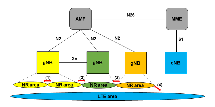
Figure 6 Handover control
(b) Inter-RAT handover
Inter-system handover between 5G SA and LTE systems, with handover from 5G SA to LTE and from LTE to 5G SA (Fig. 6(4)). There are three logical interfaces between gNBs and eNBs: N2, the logical interface between gNB and AMF, N26, the logical interface between AMF and MME, and S1, the logical interface between MME and eNB, which are used for signal processing.
3) Connection Re-establishment Control
Like LTE, the 5G SA system will support connection re-establishment control triggered by detection of cell quality degradation in UE and handover failures to recover from communications failures quickly.
4.2 Other Call Controls
1) Voice Control
In the initial phase of 5G SA service launch, the LTE system provides voice services since the 5G SA system does not support voice functionality. When providing voice services to a UE in the idle state or connected with 5G SA, redirection*35 to LTE for Evolved Packet System (EPS)*36 fallback*37 to the LTE circuit switching system is performed and voice services are provided on the LTE system.
2) Network Slicing Control
The 5G SA system supports network slicing control, which divides a single network into multiple slices for different service requirements. NTT DOCOMO plans to work on functional improvements to more flexibly provide 5G technical features such as high speed, large capacity, high reliability, low latency, and simultaneous connection of several pieces of UE in accordance with each service requirement.
3) Support for LTE-equivalent Functions
The 5G SA system also supports other procedures and messages that enable the following processing to achieve the same level of control as existing LTE systems.
- Earthquake and Tsunami Warning System (ETWS) early warning distribution
- Non-Access Stratum (NAS)*38 message transfer
- Radio Resource Control (RRC)*39 connection management
- Radio bearer*40 management
- Radio security settings
- Measurement item settings and reporting control
- NG/Xn link management between opposing nodes
- Core node: An upper-level node such as an exchange or subscriber information management unit.
- Mobility control: A control function that enables the continuous provision of incoming and outgoing communications for moving UE.
- System information: Various types of information broadcast from each cell, such as the location registration area number required for judging the need for location registration in a mobile terminal, adjacent cell information and radio-signal quality for camping in that cell, and information for restricting and controlling outgoing transmissions.
- MIB: System information necessary to receive the information simultaneously broadcast from the radio base station to the mobile terminal, and includes cellBarred status information, physical layer information, and so on.
- SIB: System information to be simultaneously broadcast from the radio base station to the mobile terminal is divided into radio blocks. Among the SIBs, SIB1 includes the UL carrier information and random-access signal composition information necessary for random access.
- Redirection: A communications technology that temporarily stops communications between mobile terminal and the network, places the mobile terminal in the idle state, and then reconnects to a cell or base station using a reconnect request signal from the UE.
- EPS: A generic term for an IP-based packet network specified by 3GPP for LTE or other access technologies.
- Fallback: The ability to switch a mobile terminal from the 5G SA system to the overlapping LTE system circuit switched domain when a voice call is made or received.
- NAS: The functional layer between the mobile terminal and core network located above the Access Stratum (AS).
- RRC: Layer 3 protocol that controls radio resources on the radio network.
- Bearer: Logical packet transmission paths set up between UPF, gNBs, UE, etc.
-
In the 5G SA service for smartphones, NTT DOCOMO has implemented NR access ...
Open
In the 5G SA service for smartphones, NTT DOCOMO has implemented NR access restriction functions to achieve safety and security. The following describes the purpose of implementing the NR access restriction function and the main features of its functions.
5.1 Background and Objectives
To maintain stable services in various environments in the era of high-speed, high-capacity mobile communications systems, communications traffic/congestion*41 control is extremely important.
Traffic control technology has been adopted and implemented in the 5G SA system to control connection request signals from UE in the radio section to preserve network equipment while ensuring connectivity for important communications such as emergency calls. The 5G SA system is also equipped with manual access restriction that enables remote monitoring technicians to execute network control*42, and automatic access restriction and staged restriction control release to reduce the load on equipment.
5.2 Main Features
The NR access restriction function has a function that allows the maintenance technician to manually implement/release restrictions, and a function that allows the gNB to automatically implement/release restrictions in consideration of the equipment load status. In addition, when the state of restriction implementation changes, the gNB notifies the operation system of the latest status as required, and the system has a function that enables the maintenance technician to monitor the restriction status of the gNB in real time.
There are four major restriction functions: “access denied restriction,” “under construction restriction” “Unified Access Control (UAC) restriction,” and “staged restriction release”.
1) Access Denied Restriction
With the access denied restriction, access from all UE is automatically restricted when the SA service cannot be provided, mainly due to equipment or circuit failures. The access denied restriction is implemented by cellBarred in system information (MIB) set to “barred.”
2) Under Construction Restriction
The under construction restriction makes it possible to allow access only for specific calls, such as those from maintenance UE, for example prior to service commencement.
The under construction restriction is implemented by cellReservedForOperatorUse in the system information (SIB1) set to “Reserved.”
3) UAC Restriction
In NR, a UAC restriction that unifies the multiple access restriction methods that exist in LTE has been newly implemented. To secure communications by controlling the inflow of calls, this restriction is used mainly in the event of equipment congestion or traffic fluctuations, by specifying the call type and restriction rate. In UAC, various communications requests at UE are mapped to one access category and one or more access identities, and gNBs can restrict each combination.
Call types are classified into access category and access identity [1], and service type units such as voice call and data can be specified as the target of restriction. In addition, the restriction rate can be specified from 0 to 100%. For example, if 30% is specified, 70% of the calls will have access and 30% will be restricted.
Maintenance technicians can monitor equipment load conditions and traffic changes and manually enforce UAC restrictions. There is also an equipment-autonomous UAC restriction function. When the gNB or an upper node becomes overloaded and is judged to be congested, the gNB automatically implements a UAC restriction with the appropriate call type and restriction rate by considering the overload status of both the gNB itself and the upper node as notified by the upper node. The determination of congestion status can be flexibly tuned by changing parameters. In addition to changes in the restriction rate, it is possible in NR to tailor restrictions to the characteristics of each piece of equipment by implementing logic to determine overload conditions for each piece of equipment.
Figure 7 shows an image of the operation of manual restriction by the maintenance technician from the operation system and automatic restriction when the upper node or gNB becomes congested. The UAC restriction is achieved by updating the setting content of barringInfoSet in system information (SIB1).
4) Staged Restriction Release
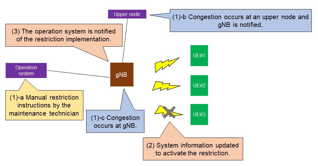
Figure 7 Operation image of manual and automatic restrictions when upper node/gNB becomes congested
To prevent massive access to gNBs and upper nodes due to a sudden influx of calls when equipment and circuits are restored, the system has a function that automatically reduces the restriction rate in stages to allow calls to enter gradually.
UAC restriction is automatically updated at regular intervals to achieve staged restriction release.
- Congestion: A state in which communications requests are concentrated for a short period of time and exceed the processing capacity of the communications control server/line, resulting in a disruption in the provision of communications services.
- Network control: Restriction of communications on the network side to secure critical communications in the event of a disaster or other situation where the concentration of communications greatly exceeds the processing capacity of communications facilities and may cause a network failure.
-
This article has described the radio base station equipment for provision of ...
Open
This article has described the radio base station equipment for provision of commercial 5G SA services. We will continue to contribute to creating an affluent society by implementing functional enhancements in a timely manner and collaborating with various partners to create services that take advantage of the features of 5G.
-
REFERENCES
Open
- [1] Y. Sagae, et al.: “5G Network,” NTT DOCOMO Technical Journal, Vol. 22, No. 2, pp. 23–39, Oct. 2020.
 https://www.docomo.ne.jp/english/binary/pdf/corporate/technology/rd/technical_journal/bn/vol22_2/vol22_2_004en.pdf (PDF format:3,106KB)
- [1] Y. Sagae, et al.: “5G Network,” NTT DOCOMO Technical Journal, Vol. 22, No. 2, pp. 23–39, Oct. 2020.

