
Special Articles on 5G SA
Overview of 5G Core Network Technologies for 5G SA
5G SA 5GC Network Slicing
Yuuta Tanaka, Masaya Arakawa, Kenzo Okuda, Kazuto Shimizu and Koichiro Kunitomo
Core Network Development Department
Abstract
NTT DOCOMO deployed the 5G Core network (5GC) to provide 5G SA and launched commercial services for enterprise customers in December 2021. 5GC leverages advanced technologies such as SBA and container infrastructure, which will enable the creation of new value required for networks in the 5G era, such as network slicing. This article describes details of these technologies.
01. Introduction
-
In the 5th Generation mobile communications system ...
Open

In the 5th Generation mobile communications system Core network (5GC)*1 that NTT DOCOMO has deployed to provide 5G Standalone (SA) *2, advanced technologies such as the two shown below are implemented.
- Service Based Architecture (SBA)*3 that provides coordination among control plane functions based on REpresentational State Transfer Application Programming Interface (REST API)*4
- Container infrastructure for easy start up and updating
These technologies make it possible to loosely couple each Network Function (NF)*5 and flexibly combine each NF according to communications applications. This will enable provision of new value required for networks in the 5G era, including network slicing*6.
This article focuses on the above two advanced technologies and their new value, network slicing, while contrasting with the previous generation 4G/Long-Term Evolution (LTE) core network*7 equipment, Evolved Packet Core (EPC)*8.
- 5GC: A core network required to support services with the characteristics of 5G, such as high reliability, low latency, simultaneous connection of multiple terminals, and high speed and large capacity.
- 5G SA: 5G deployment options in which control signals and user data are transmitted and received using the 5G radio technology, New Radio (NR). In this article, this refers to Option 2 adopted by NTT DOCOMO from among the 5G deployment options defined by 3GPP.
- SBA: One of the software architectures adopted in 5GC that connects each NF in the core network via a unified bus-type interface called SBI. Each NF can discover and interact with other NFs via SBI.
- REST API: In this article, this refers to an API that returns JSON (see *18) when accessed using HTTP/2 (see *17) with a specified URI (see *22).
- NF: Network functions that comprise the 5GC.
- Network slicing: A concept of network architecture in which logical networks (slices) are configured on the network infrastructure to provide specific network functions and network characteristics. Enables flexible service provisioning by creating, providing, and operating slices specialized for use cases and business models with different requirements.
- Core network: A network consisting of switching equipment and subscriber-information management equipment. Mobile terminals communicate with the core network via the radio access network.
- EPC: The LTE/4G core network consists of Mobility Management Entity (MME), Serving GateWay (S-GW), Packet data network GateWay (P-GW), Policy and Charging Rules Function (PCRF), etc.
-
As its initial 5G deployment model, NTT DOCOMO adopted 5G Non-Standalone ...
Open
As its initial 5G deployment model, NTT DOCOMO adopted 5G Non-Standalone (NSA)*9, in which 5G base stations are connected to the existing EPC to provide 5G services. An NSA network consists of 5G base station gNodeB (gNB)*10, 4G base station eNodeB (eNB)*11, and 4G core network (EPC) (left side of Figure 1). Since the system uses 4G equipment as well as 5G equipment, it is called 5G NSA. [1]. In this system, both 5G and 4G base stations are used for User Plane (U-Plane)*12 processing to transmit and receive user data, but only 4G base station equipment is used for Control Plane (C-Plane)*13 processing to control the signals. 5G NSA was adopted because it is possible to achieve the same quality level for C-Plane processing as 4G by using EPC, and also because it enables early deployment of 5G by utilizing existing network infrastructure.
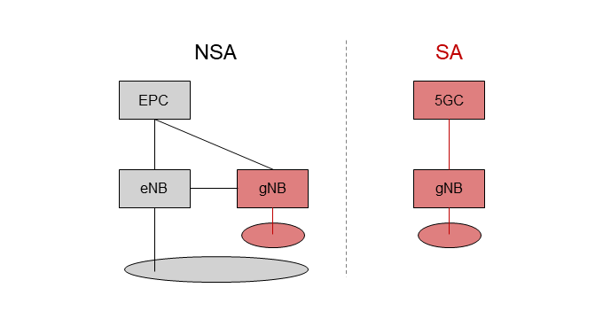
Figure 1 Network architectures of 5G NSA and 5G SA
A 5G SA network consists of gNB and the 5GC (right side of Fig. 1). The 5G SA network has a simple architecture that does not use 4G equipment, and both U-Plane and C-Plane processing are performed using 5G equipment. This network architecture enables more advanced features of 5G, such as network slicing.
The 5GC, newly introduced in the 5G SA network, consists of multiple NFs. Its architecture is shown in Figure 2. Compared to EPC, the Network Repository Function (NRF)*14 and Network Slice Selection Function (NSSF)*15 are distinctive. NRF was introduced as a repository to manage NFs. This contributes significantly to the implementation of SBA, as discussed below. NSSF was introduced in the 5GC as a dedicated NF to achieve network slicing, as described below. Most of other NFs are similar to EPC functions.
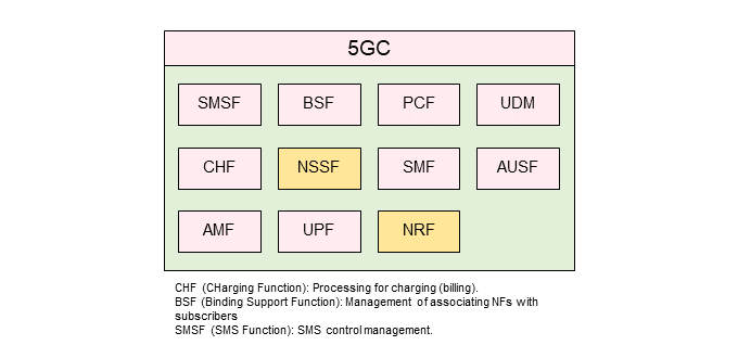
Figure 2 5GC NF architecture and the role of each NF
- 5G NSA: 5G deployment options in which control signals are exchanged on the LTE side, and NR and LTE are used in cooperative operation only for user data exchange. In this article, it refers to Option 3x, which is adopted by NTT DOCOMO from among the 5G deployment options defined by 3GPP.
- gNB: A radio base station in NR.
- eNB: A radio base station in LTE.
- U-Plane: Refers to the sending and receiving of user data.
- C-Plane: Refers to the sending and receiving of signals that control communications and other activities.
- NRF: A repository that enables discovery of NF Producers and NF Services by NF Consumer and notification when there is a change in status of registered NF Producers.
- NSSF: NF that selects the network slice to be used by the subscriber.
-
3.1 SBA Implementation
Open
SBA is used as the architecture of the 5GC system. In the 5GC, individual functions are defined as NFs, each of which provides services to other NFs [2]. The interface used in this case is the Service Based Interface (SBI). Figure 3 shows the NFs to which the SBI is applied in the 5GC. As of Release 15 (Rel-15), SBA is used in C-Plane NFs that send and receive 5GC control signals, but not in U-Plane NFs that send and receive user data.
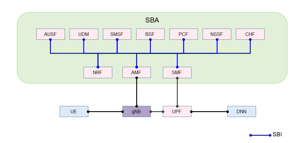
Figure 3 NFs to which SBI is applied
1) Protocol Stack*16
SBA uses HyperText Transfer Protocol version 2 (HTTP/2)*17 as the application layer protocol and JavaScript Object Notation (JSON)*18 as the notation method. In addition, the transport layer is basically required to support Transport Layer Security (TLS)*19.
2) SBI
SBI is a set of interfaces, and each NF has an interface. For example, the Access and Mobility management Function (AMF)*20 is expressed as Namf, and the Session Management Function (SMF)*21 as Nsmf. The following interfaces are defined in Rel-15 as SBI.
Namf, Nsmf, Nudm, Nnrf, Nnssf, Nausf, Nnef, Nsmsf, Nudr, Npcf, N5g-eir, Nlmf, Nnwdaf
3) REST API
In SBA, each NF uses the REST API to access each service. For example, a Uniform Resource Identifier (URI)*22 for the NF discovery service is defined in the following format in 3GPP Rel-15.
{apiRoot}/nnrf-disc/nf-instances?nfInstanceId={nfInstanceId}
3.2 Implementation of Container Infrastructure
1) Container Overview
The 5GC deployed by NTT DOCOMO leverages container infrastructure. Containers are a virtualization*23 technology that can create spaces where resources are virtually separated while sharing a host OS*24.
A guest OS is required for general Virtual Machine (VM)*25 type virtualization, but not for container-type virtualization. Due to these differences in architecture, container-type virtualization offers advantages such as being lightweight and being able to quickly start up and shut down, compared to VMs.
2) 5GC Virtualization Method in NTT DOCOMO
NTT DOCOMO has been promoting core network virtualization (Network Functions Virtualization (NFV)*26) equivalent to VM-type virtualization [3]. To implement containers, we compared (1) the VM-type virtualization method (hereinafter referred to as “VM method”), (2) the method of deploying*27 containers on VM (hereinafter referred to as “containers on VM method”), and (3) the method of deploying containers directly on physical servers (hereinafter referred to as “bare-metal container method”). The architecture of these methods is shown in Figure 4.
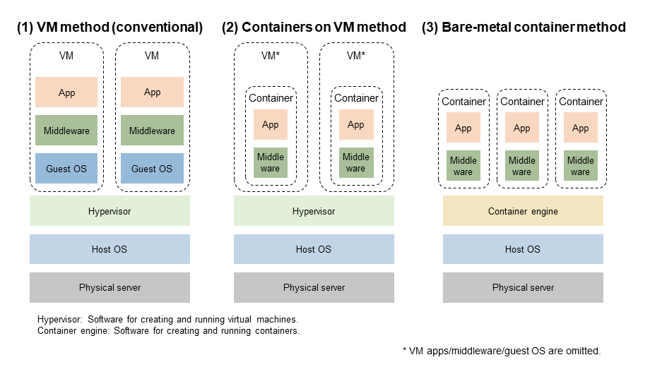
Figure 4 Architecture for each container implementation method
In method (2), as shown in Fig. 4, a multistage architecture of VMs and containers is used. For this reason, the evaluation was also conducted from the overhead*28 perspective. Table 1 shows a comparison table of these methods from NTT DOCOMO point of view. Since (1) is a conventional method and does not involve containers, (2) and (3) are compared.
Table 1 Comparison of container implementation methods
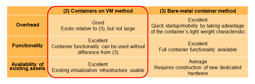
Although method (2) has a small overhead compared to method (3), there is no difference in functionality, and existing NFV infrastructure can be effectively utilized. For this reason, NTT DOCOMO basically adopted method (2). However, there are some functional blocks, such as the U-Plane processing section, for which method (1) is suitable and was adopted.
3) Architecture that Combines Microservices and Containers
As mentioned above, the 5GC uses SBA as defined in 3GPP standard. SBA is a microservice*29-aware architecture. In microservices, the unit of service is reduced in size and the interface of each service is loosely coupled, which makes it possible to add functions and make modifications quickly and flexibly [4].
In addition, each container generally executes separately and can be modified independently, making it a good match for microservices, which require independence for each service (Figure 5).
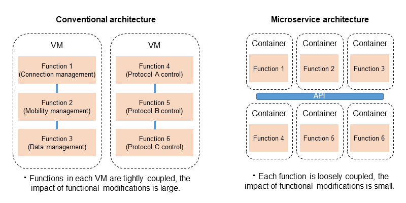
Figure 5 Microservice architecture
In architecture that combines microservices and containers, application functions are minimized compared to conventional architecture, and modification and deployment can be performed in parallel for each functional unit. This is expected to enable containers to efficiently respond with flexibility to diverse changing network demands in the network slicing described below by expanding or adding specific functions, taking advantage of the portability, rapid startup, and scalability of containers.
3.3 Network Slicing and Basic Call flows in 5GS
1) Overview of Network Slicing
Network slicing refers to the configuration of logical networks (slices) that provide specific network functions and network characteristics on a physical network. A common use of network slicing is to provide multiple networks with different characteristics that are difficult to achieve simultaneously—such as low-latency, high-reliability communications, broadband communications, and multi-terminal communications—on a single network, by performing different resource allocation for each slice [5][6].
(a) S-NSSAI
The identifier of a slice in the core network is called Single-Network Slice Selection Assistance Information (S-NSSAI)*30 (hereafter referred to as “slice ID”). With a total of 32 bits, it consists of 8 bits of Slice/Service Type (SST), which indicates the behavior of the slice with respect to functions and services, and 24 bits of Slice Differentiator (SD), which distinguishes multiple slices in the same SST. SST has a standardized range of 0 to 127, of which 1 to 5 are standard defined use cases. In addition, 128 to 255 are operator-specific (Figure 6)[5][7].
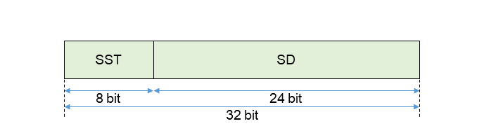
Figure 6 S-NSSAI format
(b) Number of slices
Since the maximum number of slices that one AMF or gNB can support is defined as 66559 [8], the maximum number of slices that can be used in each area is 66559. The number becomes even smaller when the signal size is considered. If the same slice ID is used in all tracking areas, the maximum number of unique slices in the entire core network is 66559 or less. Therefore, it is reasonable to consider that this is different from technology to separate U-Plane, such as a so-called virtual network*31 using an overlay network*32 on an IP network.
2) Basic Call Flows
(a) Registration*33 procedure*34
Figure 7 shows the Registration procedure performed when a User Equipment (UE) is turned on [9].
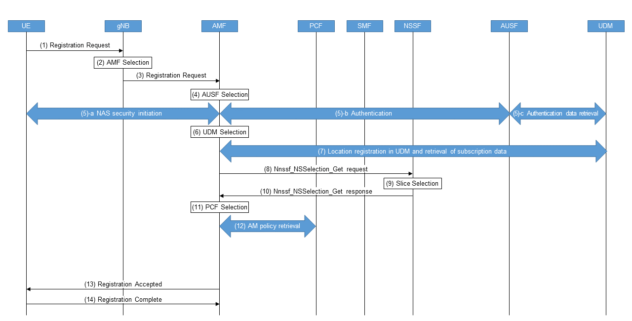
Figure 7 Registration procedure
- Steps (1) – (3): A UE sends a Registration Request message to the gNB. The gNB selects an AMF based on the slice ID requested by the UE (hereinafter referred to as “requested slice ID”) and other information, followed by sending a Registration Request message to the AMF.
- Steps (4) – (5): The AMF selects the AUthentication Server Function (AUSF)*35 based on SUbscription Permanent Identifier (SUPI)*36/SUbscription Concealed Identifier (SUCI)*37, and performs authentication based on subscription data, and security settings for radio access.
- Steps (6)–(7): The AMF selects Unified Data Management (UDM)*38 based on SUPI/SUCI to register the location and retrieve subscription data.
- Steps (8)–(10): The AMF references the requested slice ID with the subscription data in steps (1) and (3) to determine the slice ID available to the UE (hereinafter referred to as “allowed slice ID”). If the requested slice ID is not notified, the default slice ID included in the subscription data is selected. If the AMF cannot determine the allowed slice ID, such as when some or all of the requested slice IDs are not supported by the AMF, a Nnssf_NSSelection_Get request is sent from the AMF to the NSSF, and the allowed slice ID is determined from the slice selection by the NSSF.
- Steps (11)– 12): The AMF selects a Policy Control Function (PCF)*39 based on the SUPI and slice ID to obtain the AM policy.
- Steps (13)–(14): Finally, Registration Accepted message is sent to the UE containing the allowed slice ID, and Registration Complete message is returned from the UE, completing the procedure.
(b) UE-requested Protocol Data Unit (PDU) session*40 establishment procedure
Once Registration is complete, the UE requests the core network to establish a PDU session, and the UE-requested PDU session establishment procedure shown in Figure 8 is performed [9].
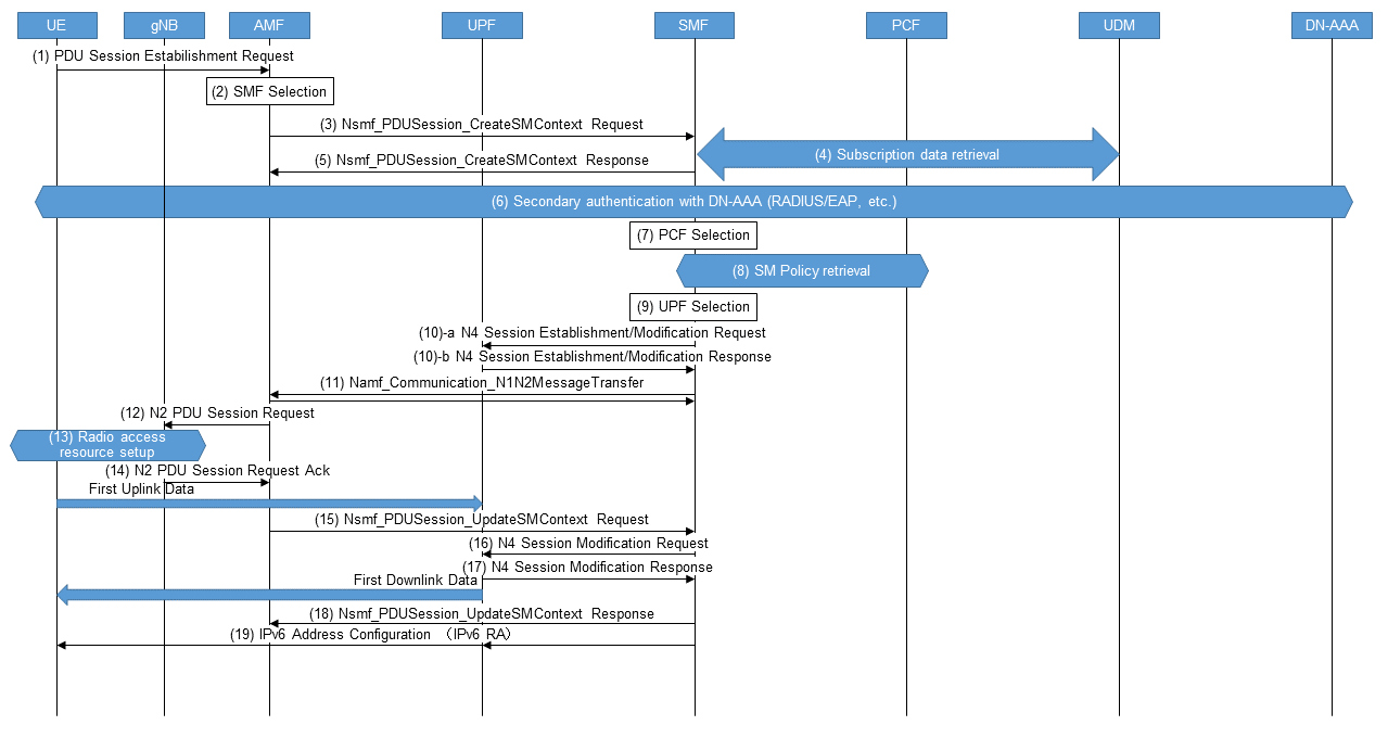
Figure 8 UE UE-requested PDU session establishment procedure
- Steps (1)–(2): A UE sends a PDU Session Establishment Request message to an AMF. The AMF selects the SMF using the requested slice ID and Data Network Name (DNN)*41, etc.
- Steps (3)–(6): The AMF requests the SMF to establish a PDU session and the SMF obtains subscription data from the UDM. The SMF determines whether secondary authentication is required based on the slice ID, DNN, and local configuration, and if necessary, performs secondary authentication for the Data Network Authentication, Authorization and Accounting (DN-AAA)*42 with Remote Authentication Dial In User Service (RADIUS)*43 protocol or the Extensible Authentication Protocol (EAP)*44, etc.
- Steps (7)–(8): The SMF selects the PCF based on the slice ID and SUPI to obtain the SM policy to be applied to the PDU session.
- Steps (9)–(10): The SMF selects a User Plane Function (UPF)*45 based on the slice ID, DNN, and UE location information, and establishes an N4*46 session with the UPF.
- Steps (11)–(18): The SMF informs the gNB via the AMF of the UPF, the radio access resources are set up, and the communications path for the uplink from the UE is established. Next, the gNB information is notified to the SMF via the AMF, and the SMF updates the N4 session and sets the forwarding destination of packets destined to the UE to the notified gNB, thereby establishing a downlink communications path to the UE. The steps up to this point constitute the communications path for uplink and downlink packets between the UE – gNB – UPF – Data Network (DN)*47 and complete the establishment of the PDU session.
- Step (19): For PDU sessions containing IPv6*48, the SMF sends an IPv6 Router Advertisement (RA)*49 to the UE via UPF to configure an IPv6 address and default gateway for the UE.
3) Characteristics of Network Slicing on Core Networks and Differences from IP Networks
(a) Characteristics of network slicing on core networks
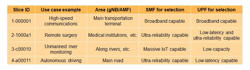
As can be seen from the aforementioned call flows, the slice ID is a parameter used to select each NF, such as SMF, UPF, and PCF, and specifies which slice ID is supported for each NF instance*50 comprising the core network. On the core network, flexible resource allocation to slices is achieved by selecting the appropriate NF instances that make up those slices according to the characteristics and uses of the slices. For example, by making the combination of SMF and UPF instances that can be selected from a particular slice ID suitable for the characteristics of the slice, as shown in Table 2, a slice for high-speed communications and a slice for low-latency communications, etc. can be constructed.
Table 2 Example of NF selection based on slice application by S-NSSAI
In the core network, it is important to accommodate and separate not only the U-Plane but also the C-Plane since mobile core network tend to have heavy C-Plane processing due to mobility management, session management, and policy control*51. Therefore, the idea of constructing slices by NF selection is reasonable.
Since slice IDs are not included in packet headers for both C-Plane message and U-Plane packet header, they cannot be directly used as unique identifiers for comprehensive resource management for network slices, including the core network and the underlying transport network*52. Instead, for the comprehensive resource management , the Quality of Service (QoS) policy in the core network associated with the slice ID could be mapped to QoS parameters in the transport layer (such as Differentiated Services Code Point (DSCP)*53), and QoS control*54 in the transport layer could be performed based on these parameters.
(b) Difference from IP networks in terms of network slicing
In the context of an IP networking, network slicing often refers to virtual networks that are logically partitioned using so-called overlay networking technologies such as Segment Routing IPv6 (SRv6)*55 and Virtual eXtensible Local Area Network (VxLAN), and management domain separation technologies such as Multi-Protocol Label Switching (MPLS)*56 and VLAN. Identifiers for virtual networks are included in the U-Plane packet header, and a router or other forwarding device selects packet forwarding tables according to these identifiers to logically divide the network. The fact that the separation of U-Plane is the main focus on an IP network shows that the design policy is very different from that of the core network.
Thus, in the core network, the slice ID is not written in the header of either C-Plane or U-Plane packets, and the slice ID is used to achieve network slicing by selecting the appropriate NF based on the communications characteristics and other factors. In contrast, IP networks achieve network slicing by assigning identifiers to the headers of U-Plane packets and classifying the packets, which is a fundamentally different architecture.
4) Implementation of Multi-access Edge Computing (MEC)*57 Using Network Slicing
MEC provides the UE with appropriate computing resources in the vicinity (hereafter referred to as “MEC resources”) and a closed connection path to them. However, a provisioning method that assigns resources on demand, as in a typical public cloud*58, is difficult to achieve using the conventional method of assigning individual DNNs for each user and setting them for the core network and UE. In addition, there may be use cases such as the Internet of Things (IoT) where the connected MEC resource needs to be changed remotely according to the location and situation. Therefore, it is necessary to be able to select the MEC resource to connect to and the SMF and UPF that accommodate the MEC resource on the core network side based on the location and subscription information of the UE without changing the DNN pre-configured in the UE.
Figure 9 shows the call flow of connections to MEC resources utilizing slice IDs in such cases.
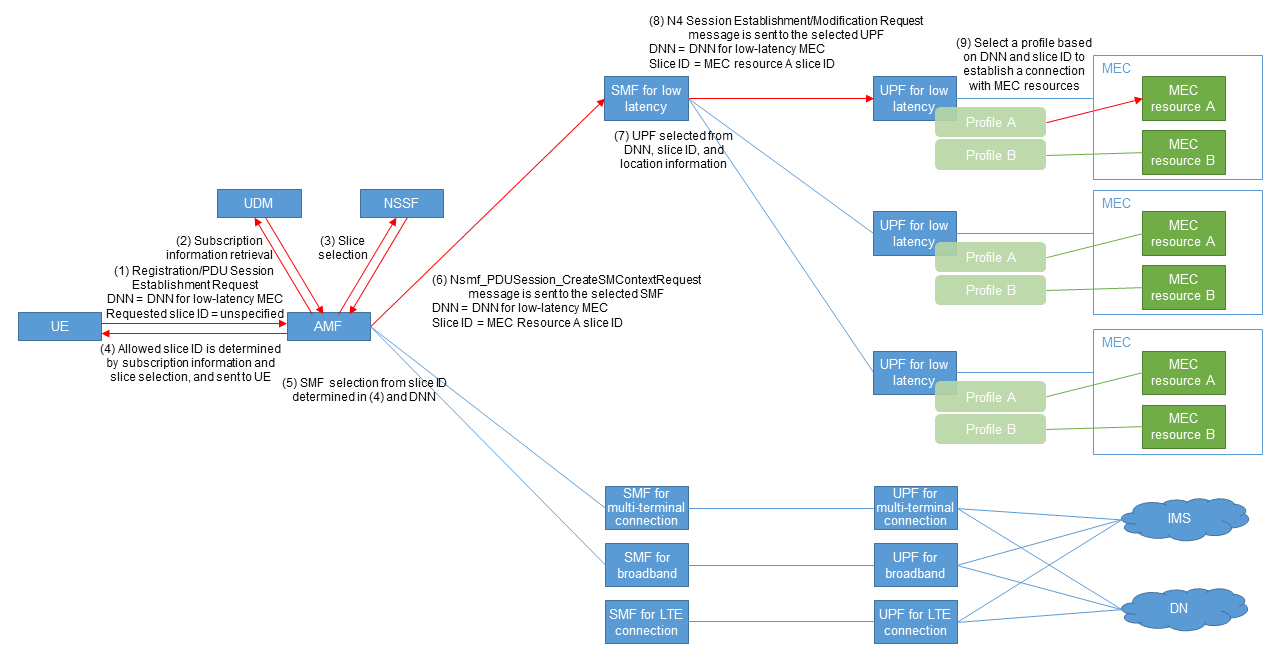
Figure 9 Connection destination selection using slice ID
- Steps (1)–(4): The requested slice ID is not pre-configured in the UE, but the DNN indicating the service—in this case, the DNN for low latency MEC—is pre-configured. The UE initiates Registration, at which time the AMF retrieves subscription information from the UDM and negotiates with the NSSF to determine the allowed slice ID, since the AMF is not notified of the requested slice ID. The AMF sends the allowed slice ID to the UE, which is the destination of communications from the UE.
- Steps (5) and (6): After registration is completed, a PDU Session Establishment Request is sent by the UE. The AMF selects a low-latency SMF based on the slice ID and DNN notified by the UE and requests PDU session establishment to the SMF.
- Steps (7)–(9): The SMF selects an appropriate low-latency-capable UPF based on the DNN, slice ID, and UE location information, and requests the UPF to establish a Packet Forwarding Control Protocol (PFCP)*59 session [10]. UPF selects a configuration profile based on the DNN and slice ID and establishes the communications path for MEC resource A based on the profile.
5) NF Selection Using Network Slicing
If UEs require different traffic characteristics on the core network, they should be accommodated in different NFs according to their characteristics. However, in cases where they are connected to the same DN, the DNN cannot be used to select the NF. Specifically, as in the case in the lower part of Fig. 9, an IoT terminal and a typical smartphone share the same DN or Internet protocol Multimedia Subsystem (IMS)*60. In such cases, different SMFs and UPFs need to be selected according to the differences in the traffic characteristics of each terminal on the core network, which is an issue that can be solved by utilizing slice IDs. First, slice IDs for the IoT subscribers and smartphone subscribers are allocated. By using slice IDs in SMF selection by AMF to have the former select SMF and UPF for massive IoT and the latter select SMF and UPF for broadband, it is possible to have these devices select NFs that are suitable for traffic characteristics. Similarly, in interworking*61 with the Evolved Packet System (EPS)*62, it is possible to prepare slice IDs to be selected when connecting from LTE to assign SMFs and UPFs with suitable performance.
- Protocol stack: Protocol hierarchy.
- HTTP/2: Communications protocol specified in Internet Engineering Task Force Request For Comment (IETF RFC) 9113.
- JSON: Data description language specified in IETF RFC 7159.
- TLS: Encryption protocol for communications specified in IETF RFC 8446, etc.
- AMF: Logical node that houses the base station (gNB) and provides mobility control, etc.
- SMF: A function in the 5G core network that manages PDU Sessions (see *40) and controls UPF (see *45) for QoS, policy enforcement, etc. Equivalent to SGW-C/PGW-C in EPC.
- URI: An identifier that represents a Web resource as defined by RFC3986.
- Virtualization: A technology that creates a virtual computing environment and hardware resources by logically dividing hardware resources such as CPUs and memory, or by emulating their operation by software. Virtualization allows physical resources to be logically divided and used.
- Host OS: A term used in contrast to guest OS (OS installed on a VM (see *25)) to indicate an OS installed on a physical server.
- VM: Technology to construct a virtual computer by means of software that emulates the operation of a computer.
- NFV: Network virtualization. Network architecture in which telecommunications carriers’ network functions are implemented in software and implemented on general-purpose hardware through virtualization technology.
- Deploy: Deploying applications, containers, VMs, etc. in their execution environment.
- Overhead: Additional processing or load that occurs outside of the intended purpose for a given process.
- Microservice: A software architecture in which an application is organized as a loosely coupled collection of smaller services with functions that communicate with each other using lightweight protocols.
- S-NSSAI: An identifier used in network slicing in the 5GC to indicate a slice with the call processing signal, used to select an NF instance.
- Virtual network: A network that is logically independent and configured on the network using management domain separation techniques such as MPLS (see *56) and VLANs, and overlay networks.
- Overlay network: Technology that configures a logically independent network on top of a physically configured network, without being bound by the physical configuration.
- Registration: In 5GS, mobile terminal registration of its current location information with the UDM (see *38).
- Procedure: Signal processing procedures implemented between base stations, between base stations and the core network, or between base stations and terminals.
- AUSF: Network functions which are responsible for authentication in the 5GC.
- SUPI: Information that identifies the subscriber in the 5G System (5GS).
- SUCI: Encrypted subscriber identification information (SUPI) used in 5GS.
- UDM: A database that stores and provides information such as subscriber data, location information, and session information in 5GC.
- PCF: A network function of the 5G core network that is responsible for QoS control (see *54), policy control (see *51), and billing control.
- PDU session: A virtual communication path for exchanging data between the UE and the data network.
- DNN: The name of the data network (see *47) to which the UE is connected via the core network.
- DN-AAA: A server that performs DN-specific user authentication, authorization, and accounting (AAA) for UE.
- RADIUS: A protocol standardized by the IETF to centrally handle AAA in a network. In the core network, it is used for authentication and authorization of UE by DNs, assigning IP addresses to UEs, and notification of data volume to DNs.
- EAP: A protocol for negotiating authentication methods standardized by the IETF. Typical authentication methods include EAP-TLS for public key authentication and EAP-TTLS for secure password authentication using TLS encryption. In 5GC, it is used as a means of negotiating authentication methods in RADIUS protocols.
- UPF: A Network Function responsible for routing and forwarding user packets, packet inspection, and QoS processing in the 5GC.
- N4: A reference point between SMF and UPF.
- DN: The external network to which the UE is connected via the core network. These include Internet Service Providers (ISPs) that provide connectivity to the Internet, third-party networks, and, in the case of closed services, the enterprise user’s network.
- IPv6: One of the communications protocols used on the Internet. It allows for a much larger number of unique IP addresses than IPv4, which is widely used today.
- RA: A signal sent from a router to notify terminals within a link of various types of IPv6 information.
- Instance: A virtual server that is made available on demand in cloud computing. A virtual server has a sporadic life cycle from start to finish. For example, it might start and finish only when a certain process takes place.
- Policy control: Technology for controlling communications in QoS, the enabling/disabling of packet transfers, or billing based on network or subscriber information.
- Transport network: The network connecting the radio access network with the core network and interconnecting equipment within each of those networks.
- DSCP: A value that indicates the priority of a packet when controlling the QoS priority of IP packets. It is represented by the first six bits of the Type of Service in the IP header. 64 levels of priority can be specified.
- QoS control: Technology to control communications quality such as priority packet transfer.
- SRv6: A source routing method in which the data source determines the intermediate route by writing segment information expressed in IPv6 (operation instructions on received packets) in the Segment Routing Header to program packet processing in the routing device on the communications path. This enables for routing control, overlay networks, etc. A segment can be associated with various instructions, such as the next destination to be sent, the routing table to be applied, and the transformation process to be applied to the packet.
- MPLS: A technology that uses label-based switching for high-speed data transfer. Networks can be logically separated by applying different routing tables based on labels.
- MEC: A computing architecture in which computing resources are deployed and made available close to the user, such as in a telecommunications station building. Compared to deployment over the Internet, it can reduce communication latency and may improve service response time.
- Public cloud: Cloud computing services that anyone can use over the Internet.
- PFCP: A C-Plane protocol used in N4 and Sx reference points for controlling U-Plane functions such as UPF/SGW-U/PGW-U. It informs U-Plane functions of packet processing rules such as packet forwarding, discarding, rewriting, dwell, priority processing, and counting.
- IMS: Refers to a group of network functions in the core network that control voice calls. It consists of Proxy-Call/Session Control Function (P-CSCF), Serving-Call/Session Control Function (S-CSCF), Application Server (AS), etc. The system is designed to be as independent as possible of transmission technologies under IP to realize voice calls over IP.
- Interwork: Interaction between communication systems.
- EPS: Generic term for an IP-based packet network specified by 3GPP for LTE and other access technologies. EPC is used as the core network for EPS.
-
This article described advanced technologies such as SBA and ...
Open
This article described advanced technologies such as SBA and container infrastructure utilized in 5GC, which were deployed to provide 5G SA, and explained network slicing that can be implemented by these technologies with deployment examples.
An example future prospect is the realization of end-to-end network slicing (hereinafter referred to as “E2ES”), which is a new added value required for networks in the 5G SA era.
E2ES is a comprehensive network slicing that spans the core network and all surrounding access, transport, and data networks and application layers. With E2ES, appropriate policy controls are applied between the applications on the UE and the server-side applications, enabling the provision of ever more demanding network services. The implementation of E2ES requires support for network slicing not only in the core network, but also in all layers of the UE, radio access network, transport network, and server-side applications. In addition, there are numerous issues such as coordinated control of QoS policies across layers, coordination and connection between slices that are implemented differently at each layer, and provisioning*63 of slices. Going forward, NTT DOCOMO will continue to address these issues and promote the development of network slicing for the DOCOMO network.
- Provisioning: Refers to the design of the network and other resources required to provide services, as well as the configuration and construction of hardware and software to run these resources.
-
REFERENCES
Open
- [1] A. Minokuchi et al.: “5G Standardization Trends at 3GPP,” NTT DOCOMO Technical Journal, Vol. 19, No. 3, pp. 5–12, Jan. 2018.
 https://www.docomo.ne.jp/english/binary/pdf/corporate/technology/rd/technical_journal/bn/vol19_3/vol19_3_002en.pdf (PDF format:1,159KB)
 - [2] A. Minokuchi et al.: “5G Core Network Standardization Trends,” NTT DOCOMO Technical Journal, Vol. 19, No. 3, pp. 48–54, Jan. 2018.
https://www.docomo.ne.jp/english/binary/pdf/corporate/technology/rd/technical_journal/bn/vol19_3/vol19_3_006en.pdf (PDF format:1,051KB) - [3] T. Kamada et al.: “Practical Implementation of Virtualization Platform in NTT DOCOMO Network,” NTT DOCOMO Technical Journal, Vol. 18, No. 1, pp. 20–28, Jul. 2016.
https://www.docomo.ne.jp/english/binary/pdf/corporate/technology/rd/technical_journal/bn/vol19_3/vol19_3_006en.pdf (PDF format:1,051KB) - [4] H. Oto et al.: “Core Network for Social Infrastructure in 5G Era,” NTT DOCOMO Technical Journal 25th Anniversary, pp. 25–34, Dec. 2018.
https://www.docomo.ne.jp/english/binary/pdf/corporate/technology/rd/technical_journal/bn/vol20_e/vol20_e_004en.pdf (PDF format:1,675KB) - [5] 3GPP TS23.501 V15.13.0: “System architecture for the 5G System (5GS); Stage 2,” Mar. 2022.
- [6] K. Aoyagi et al.: “5G Advanced Technologies for Creating Industries and Co-creating Solutions,” NTT DOCOMO Technical Journal, Vol. 22, No. 3, pp. 71–89, Jan. 2021.
https://www.docomo.ne.jp/english/binary/pdf/corporate/technology/rd/technical_journal/bn/vol22_3/vol22_3_008en.pdf (PDF format:2,081KB) - [7] 3GPP TS23.003 V15.11.0: “Numbering, addressing and identification,” Dec. 2021.
- [8] 3GPP TS38.413 V16.10.0: “NG-RAN; NG Application Protocol (NGAP),” Jun. 2022.
- [9] 3GPP TS23.502 V15.16.0: “Procedures for the 5G System (5GS); Stage 2,” Jun. 2022.
- [10] Y. Miyazaki et al.: “CUPS for Flexible U-Plane Processing Based on Traffic Characteristics,” NTT DOCOMO Technical Journal, Vol. 23, No. 3, pp. 38–51, Jan. 2022.
https://www.docomo.ne.jp/english/binary/pdf/corporate/technology/rd/technical_journal/vol23_3/vol23_3_005en.pdf (PDF format:1,355KB)
- [1] A. Minokuchi et al.: “5G Standardization Trends at 3GPP,” NTT DOCOMO Technical Journal, Vol. 19, No. 3, pp. 5–12, Jan. 2018.

