
Special Articles on 3GPP Release 17 Standardization Activities
Overview of 5G Core Network Advanced Technologies in 3GPP Release 17 —Core Network and Terminals—
NAS/SBA Signal Enhancements SOR 5GC Restoration Procedures
Hiroshi Ishikawa
R&D Strategy Department
Maoki Hikosaka
Communication Device Development Department
Shin Nishida
Core Network Development Department
Ban AI-Bakri
MeadowCom
Abstract
The 3GPP CT Group defines protocols that satisfy requirements for services and architectures defined mainly by the SA Group. The CT Group also specifies some functional enhancements when updates or changes to the architecture are not needed. This article describes some of the functional enhancements in Release 17 that came to the attention of NTT DOCOMO, such as PLMN selection, Steering of Roaming, and procedures for restoring UDR-related profiles, as well as some of the protocol enhancements for NAS and service-based interfaces.
01. Introduction
-
The 3rd Generation Partnership Project (3GPP)*1 ...
Open

The 3rd Generation Partnership Project (3GPP)*1 Core network and Terminals (CT)*2 Group handles mainly the definition of protocols to support the requirements of 3GPP services and architectures. It is also responsible for defining architectural requirements themselves, for some specific features such as Steering Of Roaming (SOR)*3, Public Land Mobile Network (PLMN)*4 selection, restoration procedures, Public Warning Systems (PWS)*5, and Stage2 of Numbering, addressing and Identification. For Rel-17, the CT Group worked mainly on functional enhancements to 5th Generation mobile communication systems (5G) and on enhancements to related protocols.
This article describes solutions and enhancements introduced into 3GPP CT specifications in Rel-17, mainly addressing features that are of interest to operators. This includes enhancement of Control Plane SOR (eCPSOR)*6, Restoration of Profiles related to User Data Repository (ReP_UDR)*7, Public Land Mobile Network (PLMN) selection (support for Minimization of service INTerruption (MINT)*8, and 5GC architecture for SATellite networks (5GSAT)*9 support).
- 3GPP: An organization that creates standards for mobile communications systems.
- CT: The group within 3GPP that specifies protocols used within the Core Network (see *57) and between mobile terminals and the Core Network.
- SOR: A function to prioritize selection of operators. A mechanism by which HPLMN (see *10) can specify which VPLMN (see *12) a UE will select, from among multiple VPLMN that may be available.
- PLMN: An operator that provides services using a mobile communications system.
- PWS: A system function for delivering disaster and other urgent information with the highest priority in real time.
- eCPSOR: A type of SOR (controlling operator selection priority) specified by 3GPP and an extended version of CP-SOR (see *14), which notifies of operator priorities using the Control Plane, rather than using SMS, as was done earlier.
- ReP_UDR: An item under study at 3GPP, specifying restoration procedures to maintain network service continuity in cases when the reliability of data stored in UDR (see *23) decreases (if data is corrupted by DB corruption, etc.).
- MINT: A function to minimize effects on the user if the network is affected by disaster, specified in 3GPP Release 17.
- 5GSAT: Function required to support NR satellite access, which is specified in 3GPP Release 17.
-
SOR is a function that enables the home operator ...
Open
SOR is a function that enables the home operator (Home PLMN (HPLMN))*10 to designate priorities to direct roaming*11 subscribers to a preferred Visited PLMN (VPLMN)*12 among multiple VPLMN at the roaming location [1]. This function has been in use since Global System for Mobile communications (GSM)*13.
In 5G, a solution called Control Plane SOR (CP-SOR)*14 was introduced, which provided SOR information (SOR-info)*15 over the control plane*16. SOR-info includes the home operator priorities of VPLMNs to which the user terminal (User Equipment (UE))*17 should select and connect to.
The UE must wait until it enters the Idle state before performing SOR, and previously when a UE in the Connected state received SOR-info, it would wait until it entered the Idle state before connecting to the preferred operator. In such cases, regardless of whether the HPLMN had specified a preferred VPLMN (usually a foreign operator) based on roaming connection costs, the subscriber's profile*18 and other factors, SOR would not be performed for quite some time.
As such, Rel-17 specifies enforced CPSOR (eCPSOR), enabling the HPLMN to interrupt an ongoing PDU session*19 to perform SOR, by requesting the UE to move to Idle state. Simply interrupting the session and transitioning to the Idle state can interrupt communication and other services currently in use, degrading the user experience, so the HPLMN can specify communication types (e.g.: voice communication), and the UE will give priority to those communication types. For this CP-SOR functional enhancement, additional information called SOR Connected Mode Control Information (SOR-CMCI)*20 can be sent in the SOR-info. A detailed explanation of UE control using SOR-CMCI, SOR-CMCI Provisioning*21, SOR-CMCI organization and storage within the UE is given below.
2.1 UE Operation Control with SOR-CMCI
SOR-CMCI is information specifying the type of communication to be prioritized more than SOR, and enables control of the timing of transition of a Roaming UE from Connected to Idle states, followed by SOR execution, according to the type of communication in progress. Specifically, if a UE is performing a type of communication specified in the SOR-CMCI, the UE will either end that communication, or wait an amount of time specified in the SOR-CMCI before performing SOR. This enables the HPLMN to control when selection of the priority network operator (PLMN selection) begins.
In 3GPP Rel-17, SOR-CMCI support is mandatory on UE, but is optional on HPLMN, so whether it is available will depend on policies of the operator.
2.2 SOR-CMCI Provisioning by the HPLMN
The SOR-info information, including SOR-CMCI, is dynamically generated by the Application Function for SOR (SOR-AF)*21 or provided by the HPLMN Unified Data Repository (UDR)*22, and managed by the HPLMN (Figure. 1). This information can be provided to the UE when the UE registers with a VPLMN, after registration has completed. The HPLMN can also configure SOR-CMCI in a UE when the UE is being served by the HPLMN.
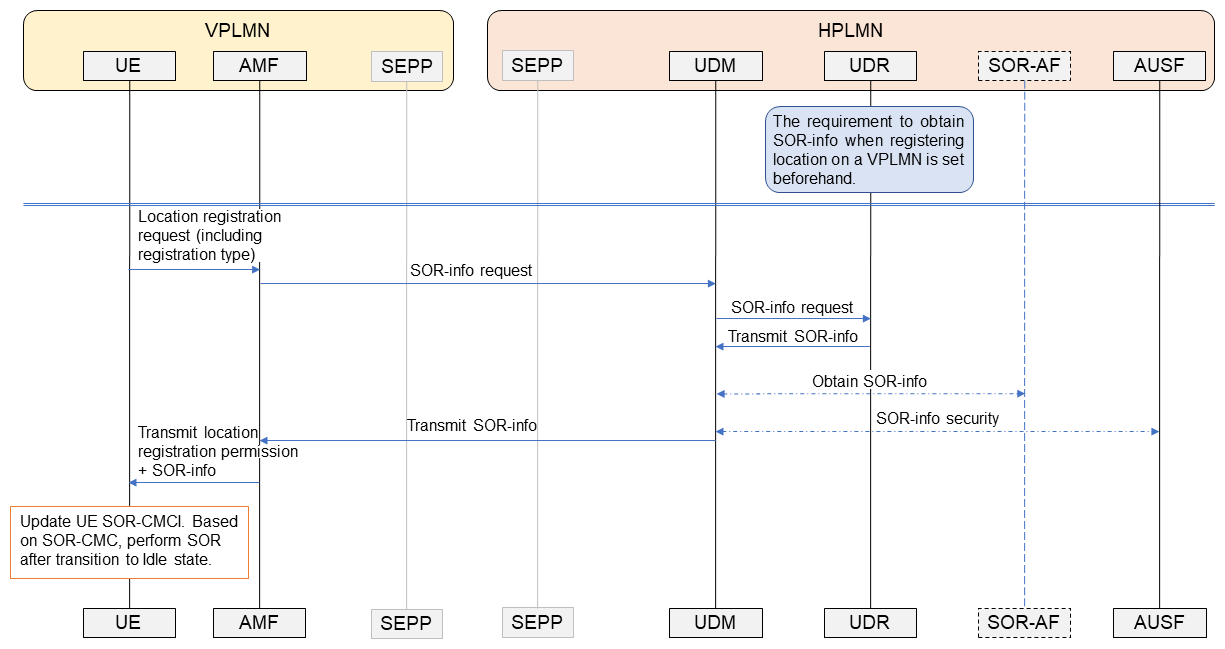
Figure 1 Transmission of SOR-CMCI from home operator to a roaming UE (during location registration)
SOR-CMCI related information must be exchanged securely between the HPLMN Unified Data Management (UDM)*23 and the UE. The HPLMN UDM uses the AUthentication Server Function (AUSF)*24 to maintain security of this information. SOR-info is transmitted transparently from the HPLMN network through the VPLMN to the UE, and the UE can verify that it has not been altered by the VPLMN using previously held security information and procedures performed by the AUSF to guarantee completeness. When the HPLMN sends the SOR-info, it can also request the UE to return notification that it received the information safely.
2.3 SOR-CMCI Parameter(s)
SOR-CMCI is composed of SOR-CMCI rules, and each rule is composed of the following parameters [2].
(a) Type of communication. The HPLMN can use this to specify the type of communication to prioritize on the UE, and is composed of the following information.
- Packet Data Unit (PDU)*25 session attribute type criterion. This can be used to specify the context of the PDU session established with the UE, including the slice, connected Data Network Name (DNN)*26, etc.
- Service type criterion. To specify the type of service performed on the UE, such as voice call, video call, Short Message Service (SMS), etc.
- SOR security verification criterion. To specify whether the UE failed the SOR-info security check or not.
- Match-all type criterion. Used when there is no criteria for matching a definition in the SOR-CMCI with the UE PDU session or service.
(b) Timer values associated with each communication type
If there is a match with criteria specified in (a), the UE will transition to the Idle state after the corresponding timer value here elapses.
2.4 Storage of the SOR-CMCI on the UE
The SOR-CMCI is stored in a Universal Subscriber Identity Module (USIM)*27 or in non-volatile memory on the UE itself. This requirement was introduced for cases when the UE is roaming to a VPLMN where the HPLMN cannot transmit the SOR-CMCI to the UE because, for example, the VPLMN is only Rel-16 compliant. The HPLMN can transmit the SOR-CMCI to the UE beforehand, and have the UE store it. Note that SOR-CMCI stored in non-volatile memory will take priority over SOR-CMCI stored in a USIM.
- HPLMN: The operator where the user is a subscriber; their home operator.
- Roaming: A mechanism by which a user can use services similar to those of the operator to which they have subscribed, even if they are outside of that operator's service area, as long as they are within the service area of another participating operator.
- VPLMN: The operator at the location where a subscriber is roaming (serving operator).
- GSM: A 2nd Generation mobile communications system used by digital mobile phones.
- CP-SOR: A type of Steering of Roaming (prioritization of operator selection) which uses the Control Plane to indicate operator priorities rather than SMS, which was used previously.
- SOR-info: Information used for SOR that the UDM (see *24) sends to UE when implementing CP-SOR. Includes a list of operator priorities, information for verifying correct reception, etc.
- Control plane: The control process for communication data transmission paths, etc.
- User equipment: A mobile device with functionality conforming to 3GPP specifications.
- Subscriber profile: Information needed for service control, including subscription, user settings, serving cell data, etc.
- PDU session: The virtual communication path used for exchange of data.
- SOR-CMCI: Information controlling the timing for the UE to transition from Connected to Idle state when the HPLMN performs SOR on the UE.
- Provisioning: Notifying equipment being managed of the information it requires, and performing the configuration.
- SOR-AF: An application function that generates steering-related information that is sent to UE, providing encrypted data (in secured packets) that includes the priority operator list, SOR-CMCI, etc.
- UDR: A repository in the 5GC with a defined structure. Stores subscriber information and the states of subscribers and certain equipment.
- UDM: An information management facility in 5GC that stores and provides information including subscriber data, UE contexts (area of attach, session information, etc.). Performs mainly application processing, such as exchange with other equipment and actual data is stored and extracted by a UDR.
- AUSF: An NF of the 5GC that authenticates subscribers and authorizes access to the network by UE.
- PDU: A unit of data processed by a protocol layer/sublayer.
- DNN: The name of a data network to which UE connect. When a UE establishes a PDU session for communication, it specifies a DNN.
-
3.1 MINT
Open
MINT is a feature that was introduced to minimize any effects on users when the network is unable to provide services, such as when an earthquake, tsunami or other disaster occurs. Introduction of the MINT feature was based on requirements from South Korea, and is optional for both UE and network. The HPLMN can configure the UE to use this feature or not. Use of the feature also assumes arrangements have been made between the operators involved.
1) Procedure for Using the MINT Feature
If users are not able to use a PLMN that they are normally permitted to use, the MINT feature enables them to temporarily roam to a PLMN they would normally not be permitted to access. The overall process for using the MINT feature is shown in Figure 2. If the HPLMN has enabled the MINT feature and a disaster occurs so that the UE can no longer use PLMN-1, which had been serving the UE, the UE will recognize that PLMN-1 is unavailable due to disaster conditions (Fig. 2(1)). This is determined when the UE receives system information from another PLMN. For example, if PLMN-2 recognizes that PLMN-1 is under “disaster condition”, PLMN-2 will notify all UE within its coverage that PLMN-1 is under disaster conditions by including the PLMN-ID for PLMN-1 in its list of PLMN under disaster conditions that are allowed to roam from other networks during a disaster.
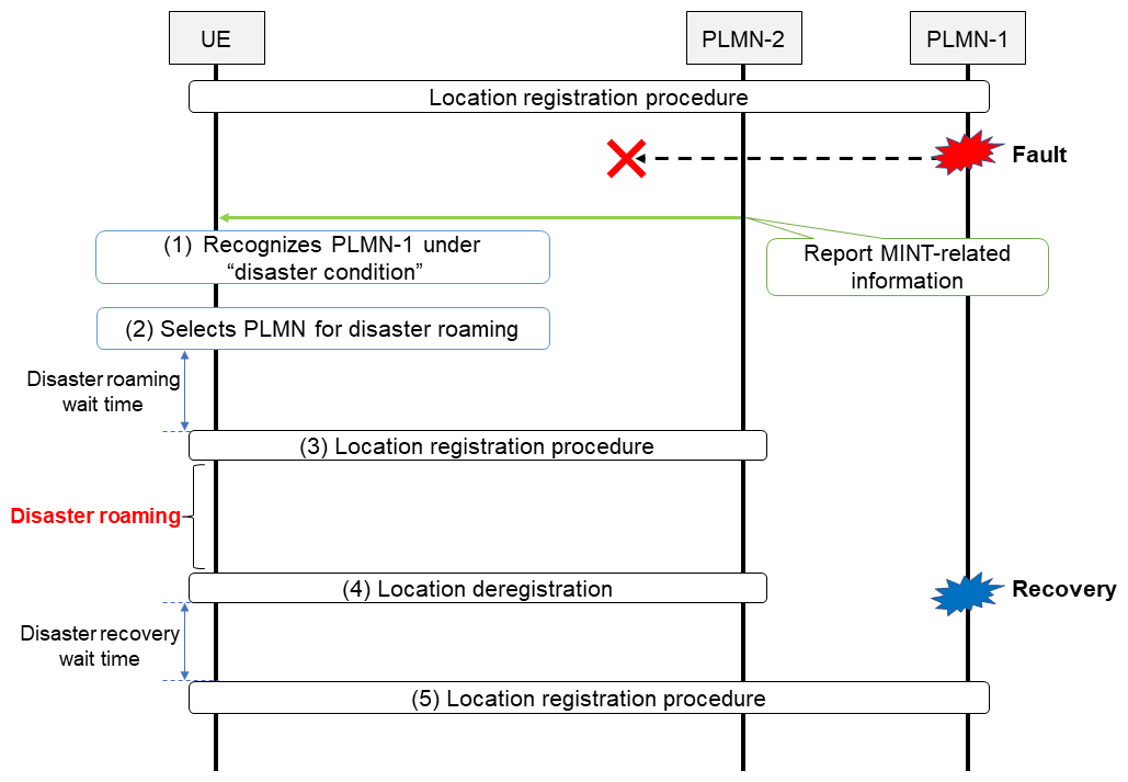
Figure 2 Overall process when using the MINT function
Then, the UE will select a PLMN for disaster roaming satisfying either of the following (Fig. 2(2)).
- A PLMN included in the “list of PLMN to be used in disaster conditions”.
- A PLMN that broadcasts the system information for MINT
The list of PLMN to be used during disaster conditions is provided to UE beforehand by the VPLMN or HPLMN. Note that if the UE receives a list from the VPLMN, that list takes priority over a list provided by the UE's HPLMN, but the UE can only use the list from the VPLMN if the HPLMN has configured the UE to be able to apply a list from that VPLMN.
2) Disaster Roaming Wait Range
In fact, when roaming during a disaster using the MINT function, large numbers of UE in the disaster area could potentially access a PLMN at the same time, so the chance of network overload must be minimized. To do so, a “disaster roaming wait range” is configured in the UE beforehand. In Fig. 2(2), after selecting a PLMN for disaster roaming, the UE will wait for a random time period within the disaster roaming wait range, before it attempts to access the disaster roaming PLMN. When doing so, the UE notifies the network that it is connecting for disaster roaming in its registration request message (Fig. 2(3)).
When the damaged network has been restored and disaster roaming is no longer needed, the network will either reject access or deregister the UE (Fig. 2(4)). Note that when returning to its original PLMN, it will also wait a random time period within a specified “disaster return wait range” (provided during registration or set in the USIM) before returning to the original PLMN, to minimize the chance of overloading that network (Fig. 2(5)).
3.2 NR Satellite Access
New Radio (NR) satellite access is a scheme supported in Rel-17 that enables UE on the ground to communicate with base stations on satellites. With NR satellite access, cells can be created over wide areas covering whole countries or multiple countries. When a UE supporting satellite access is within a satellite access cell, that cell will be a candidate for PLMN selection.
1) Information that can be Set in the USIM
To enhance PLMN selection to include NR satellite access, the following information can be stored in the USIM.
- Radio Access Technology (RAT) prioritization for satellite access
- Higher priority PLMN search period during satellite access
RAT prioritization for satellite access is used by UE when selecting a PLMN. This enables, for example, satellite access to be given higher priority than ordinary access methods. When a UE is roaming, it generally searches for a higher priority PLMN periodically, but this enables a different search period to be set for satellite access in the USIM.
2) Rejection of Connection Requests from UE that are Outside the Country
Satellite access cells can cover multiple countries, but each country and region has its own regulations and lawful interception requirements, so in some cases, an operator cannot provide service to UE that are not within its country. As such, a network must be able to reject connection requests from UE that are outside the country. In such cases, the network obtains UE location information, uses it to determine whether the UE can connect, and if rejecting the connection request, notifies the UE that “PLMN not allowed to operate at the present UE location.” To avoid sending further connection requests to that network, upon receiving the rejection message, the UE stores the following information.
- The PLMN ID of the satellite access cell
- The current geographical location of the UE when it received the rejection message, if possible
Then, the UE starts a timer associated with the stored information, which is dependent on the UE implementation, and also computes the distance between the current UE location and the location when it received the rejection message from the PLMN. While the timer is running and while the UE is within a set distance of where it received the rejection message, the UE will not send a further connection request to that satellite access network.
-
Password Authentication Protocol (PAP)*28 and ...
Open
Password Authentication Protocol (PAP)*28 and Challenge Handshake Authentication Protocol (CHAP)*29 are used to authenticate users when connecting to a data network. They are supported by Evolved Packet System (EPS)*30 but in Rel-15 of the 5G System (5GS) specifications, it was not initially clear whether it must be supported or not.
However, for the following reasons, support has been made explicit in the 5GS specifications.
- With EPS, PAP and CHAP are used for connecting to some enterprise networks, including servers for Data Network Authentication, Authorization and Accounting (DN-AAA)*31 that support PAP/CHAP authentication. These are used by some third parties, so support must continue when migrating from EPS to 5GS.
- When deploying 5GS networks, and particularly a stand-alone*32 Session Management Function (SMF)*33, third-party operated DN-AAA servers and local networks could need to support PAP/CHAP authentication.
To ensure backward compatibility when UE support PAP and CHAP in a 5GS network, Rel-15 and Rel-16 have a provisional regulation enabling UE to send PAP/CHAP identifiers in the extended Protocol Configuration Options (ePCO)*34, which are sent by Non-Access Stratum (NAS)*35 protocol.
On the other hand, in Rel-17 both UE and network support PAP/CHAP ePCO parameters, and exchange with SMF and DN-AAA servers is defined for performing PAP/CHAP authentication.
When a UE establishes a new PDU session with a data network, it can include PAP/CHAP protocol parameters in the ePCO, based on UE settings for that data network. The SMF determines whether use of PAP/CHAP is accepted based on policies associated with the external data network and the UE subscriber information.
- USIM: Another name for a SIM or SIM card.
- PAP: A protocol for authenticating users, widely used by internet providers and others.
- CHAP: A protocol for authenticating users. It enhances security by encapsulating authentication information.
- EPS: Generic term for an IP-based packet network specified by 3GPP for LTE or other access technologies.
- DN-AAA: Authentication between the data network and the UE.
- Standalone: A deployment scenario using only NR, in contrast with non-standalone operation which uses LTE-NR DC to coordinate existing LTE/LTE-Advanced and NR.
- SMF: The functional section that manages sessions in 5GC. Equivalent to SGW-C/PGW-C in EPC.
- ePCO: Information exchanged between network and UE on the NAS. Transmits protocol configuration information used for communication between the data network and the UE.
-
5.1 Role of UDRs and Effects when They Are Damaged
Open
In the 5GC, context*36 information such as subscriber data and the state of the subscriber's UE are stored in a UDR. If the data stored in the UDR becomes corrupted due to equipment failure or other cause, the subscriber data and/or state could become inconsistent with that stored in UDR and/or with that maintained by other entities*37, and in such a case it will no longer be possible to provide network services requiring the latest subscriber information and location. For example, if the latest location information is lost, voice terminating calls could fail, or services based on the latest subscription may not be available. Failure of Terminating Access Domain Selection (T-ADS)*38, which determines the appropriate domain for delivering Short Message-Mobile Terminated (SM-MT)*39 SMS, or voice terminating calls by the Internet protocol Multimedia Subsystem (IMS)*40 could occur.
5.2 “Reset” Function for UDR Specified in Rel-17
Before 5GC was introduced, 3GPP specified recovery procedures using a Reset[3],[4] that are used if the network determines that it cannot guarantee subscriber data and the context state stored in the Home Subscriber Server (HSS)*41, and Home Location Register (HLR)*42 are consistent with that maintained by other entities.
On the other hand, the 5GC uses Data Layered Architecture (DLA)*43, so that it does not lose stateful*44 data, and it should not lose consistency of status information that will affect network services. As such, 5GC did not initially specify a function similar to “Reset” as in the earlier system. However, various scenarios where a “Reset” would be needed from an operational perspective were identified, such as when data becomes inconsistent due to backup stored at a remote location, or when equipment failure is identified by an operator when measures are taken to synchronize subscription data. As a result, a function similar to reset was specified in Rel-17 under a Work Item called Restoration of Profiles related to UDR (ReP_UDR).
This function enables profiles to be restored between UDRs and consumers*45 of UDR-related Network Functions (NF) (UDR Consumers) such as UDM, the Policy Control Function (PCF)*46 and the Network Exposure Function (NEF)*47, as well as between UDM and consumers of UDM-related NF such as the Access and Mobility management Function (AMF)*48, SMF, the Short Message Service Function (SMSF)*49 and AUSF. It enables the latest status to be maintained as much as possible, even if data stored in a UDR is lost or corrupted (Figure 3).
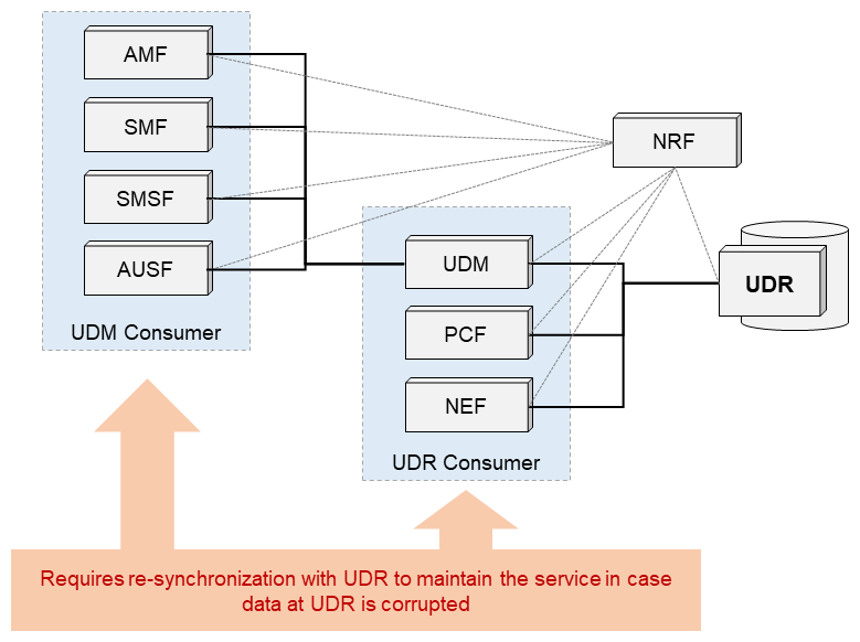
Figure 3 NFs involved in restoration of UDR-related profiles
5.3 Regime and Procedures for UDR Recovery
Under normal operation, data stored in the UDR is automatically updated. The most important information stored in the UDR is the location of each UE, followed by other important information such as callback information, which is required to update the subscription and policy data. The loss or corruption of these data would seriously impact services offered to subscribers, so a regime and procedures were specified to restore the information automatically and limit the effects of UDR failure.
This regime assumes using replication of volatile storage units and periodic back-up of data. Procedures are specified for cases when the integrity of data in the UDR cannot be ensured, including when relying on the periodically backed-up data.
These procedures are basically divided into three phases as follows (Figure 4).
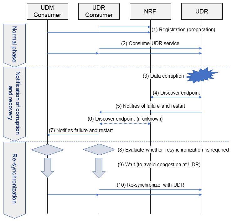
Figure 4 UDR related profile recovery
1) Phase 1: Normal Phase
The UDR/UDM Consumer registers with the Network Repository Function (NRF)*50. In doing so, the UDR/UDM Consumer provides its own address as the NRF to receive notifications (a Callback Uniform Resource Identifier, or “Callback URI”*51) (Fig. 4(1)) and as necessary, it notifies the UDR or UDM of an address to be notified when resynchronization with the UDR/UDM Consumer is necessary. The UDR/UDM Consumer then uses UDR/UDM service normally (Fig. 4(2)).
2) Phase 2: Notification of Corruption and Recovery
If the UDR data is corrupted (Fig. 4(3)), the corrupted UDR data is recovered from backup, and the UDR notifies the consumer that it has been corrupted and recovered (Fig. 4(5)). In doing so, if necessary, it sends a query to the NRF to discover the NF Consumer end point*52 (Fig. 4(4)). If the UDR Consumer is a UDM, the UDM also notifies the UDM Consumer (Fig. 4(7)). Before this notification, if necessary, the UDM queries the NRF (Fig. 4(6)) to determine the UDM Consumer.
3) Phase 3: Re-synchronization
When a UDR/UDM Consumer is notified that UDR data has been corrupted and recovered, the UDR/UDM Consumer must evaluate whether any related data stored in the UDR must be resynchronized to maintain or update the latest status (Fig. 4(8)). If the UDR/UDM Consumer cannot ensure that the relationship between its data maintained in the UDR is reliable, all related end-user data is resynchronized (Fig. 4(10)).
5.4 New Functional Enhancements
To implement these three phases, the following enhancements have been specified.
1) Preparation of UDR and UDR/UDM Consumer Profiles
Upon registration, a callback URI is provided to the UDR for sending notifications from the UDR to the UDR/UDM Consumer. A callback URI is also provided by the UDR/UDM Consumer when it registers with the NRF.
The UDR notifies the UDR/UDM Consumer of information related to registration and authentication times and a Reset ID. This information is used later to determine the need for and instructions for initiating resynchronization.
2) Path for Notifications from UDR to UDR/UDM Consumers
When the UDR detects corruption or inconsistency in the data it stores, it notifies UDR/UDM Consumers of the fact. Callback URIs used for this notification are obtained from the NRF, which the UDR/UDM Consumer registered/configured during the Normal Phase. If the UDM is a UDR Consumer, the notification is also sent from the UDM to that UDM Consumer.
3) Notification Content
The notification sent from UDR to UDR/UDM Consumer contains the time of the latest replication and recovery (between these two time, data could have been corrupted on the UDR or an inconsistency between UDR and UDR Consumer could have occurred. See Figure 5 for details), and can also include the ranges of SUbscription Permanent Identifiers (SUPI)*53 or Generic Public Subscription Identifiers (GPSI)*54 that could be affected, the unique Reset-ID that was created in the preparation phase (1) above, the Single-Network Slice Selection Assistance Information (S-NSSAI)*55, DNN, and PLMN ID, a UDM Group ID, and UDR PLMN ID.
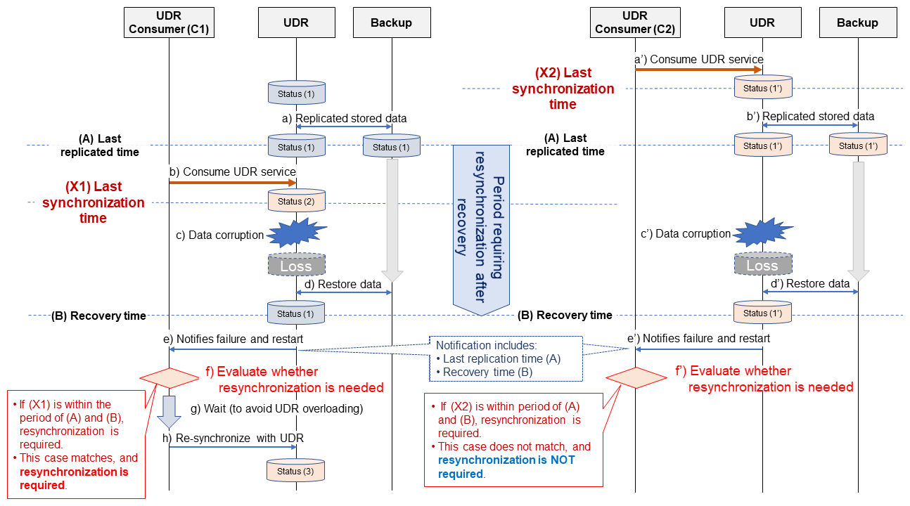
Figure 5 Determining whether resynchronization by UDR Consumer is necessary when receiving a fault notification
4) Synchronization Triggers
The timing for a UDR/UDM Consumer to respond when it receives a resynchronization or other notification from a UDR is dependent on the implementation of each UDR/UDM Consumer and policies of the communications operator.
5) Synchronization Procedure
Each UDR/UDM Consumer will attempt to re-use the UDR service, either directly with the UDR, or through the UDM. If the NF consumer is either AMF/SMF/SMSF/AUSF, these NFs will notify the UDM, setting a dedicated flag (udrRestartInd) indicating that they are registered for resynchronization. This enables the UDR to determine a suitable process for the profile.
- NAS: A functional layer between the core network and the UE, above the Access Stratum (AS).
- Context: State or status information regarding the relevant subscriber or equipment.
- Entity: A structural element that provides functionality within a logical architecture.
- T-ADS: A function that determines whether a call should be delivered over IMS or CS. This is determined based on the characteristics of the access network serving the UE, characteristics of voice support on that access network, and other factors.
- SM-MT: Receiving SMS message as the recipient.
- IMS: A call control procedure that realizes multimedia communications by consolidating 3GPP standardized communication services offered over fixed and mobile networks through the use of SIP (see *60), which is a protocol used on the Internet and in Internet phones.
- HSS: A subscriber information database in a 3GPP mobile communication network that manages authentication information and network visiting information.
- HLR: A logical node defined by the 3GPP with functions for managing subscriber information and call processing.
- DLA: A structure in which equipment that stores data and front-end equipment that uses data is separate.
- Stateful: A property of a mechanism that stores state, and uses it in processing events that occur later. The opposite is a stateless mechanism, which stores no state, and processes only according to input as it is received.
- NF Consumer: An NF that uses/consumes an NF service provided by an NF Producer.
- PCF: An NF in 5GC responsible for policy control, such as QoS and billing control.
- NEF: An NF in 5GC that provides APIs for obtaining internal 5GC information or controlling within the 5GC from applications outside of 5GC.
- AMF: An NF in 5GC that serves the UE in a particular area.
- SMSF: An NF in 5GC that handles SMS through the NAS.
- NRF: An NF in 5GC to achieve Discovery of NF Producer or NF Service by an NF Consumer, and Management allowing NF Producers to register to NF as well as to allowing notifications upon change of registered information.
- URI: An identifier that represents a Web resource as defined by Request For Comments 3986 (RFC3986).
- End point: URI to access an API.
- SUPI: An identifier for subscribers, specified by the 3GPP and used by the 5GS.
- GPSI: An identifier for external users, specified by the 3GPP.
-
1) SMS Extensions Related to Architectures and Protocols Used in 5GC
Open
SMS support has been specified since GSM, and message delivery within the core network*56 has been implemented using the Mobile Application Part (MAP)*57 protocol. The protocol was later updated gradually, to use the Diameter*58 protocol in EPC and then to use Session Initiation Protocol (SIP)*59 over IMS.
For 5GC, the initial release (Rel-15) introduced SMSF, which used the NAS to handle SMS messages between UE and core network, but delivery within the core network still used existing network protocols. For Rel-17, work was done to introduce service-based interfaces for delivering SMS within the core network.
- A service-based interface is supported and existing SMS related entities were enhanced to support specification of a new service-based Application Programming Interface (API)*60.
- Procedures using service-based interfaces for SMS Mobile Terminated and Mobile Originated (SMS MT/MO).
- Support for mapping from GPSI (e.g.: phone number) to subscription.
- Use of N32 for non-roaming purposes such as SMS-message transfer between operators (PLMN).
Entities for implementing SMS using a service-based architecture and related APIs are shown in Figure 6 and specified in reference [5]. These include newly specified service-based APIs for entities that existed before the 5GC was specified (Interworking MSC For Short Message Service (SMS-IWMSC)*62, Gateway MSC For Short Message Service (SMS-GMSC)*63, IP-SM-GW and SMS Router), APIs for NF services already in the 5GC that have been enhanced (NRF, AMF), and newly specified NF services among the service APIs already in the 5GC (SMSF, UDM).
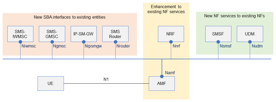
Figure 6 Entities and related APIs for implementing SMS using a service-based architecture
2) Enhancements to SEPP and N32 for Inter-operator SMS Connectivity
In Rel-15 3GPP specified an entity called the Secure Edge Protection Proxy (SEPP)*64 for the first time (Figure 7). This entity is positioned at the edge (or boundary) of a PLMN and handles transmission of signals between different PLMN by exchange with the SEPP on other PLMN. The SEPPs in the two PLMN establish a connection as specified by the N32 interface, which can relay signals transmitted between NFs on the two different PLMNs. The N32 connection is established in two steps.
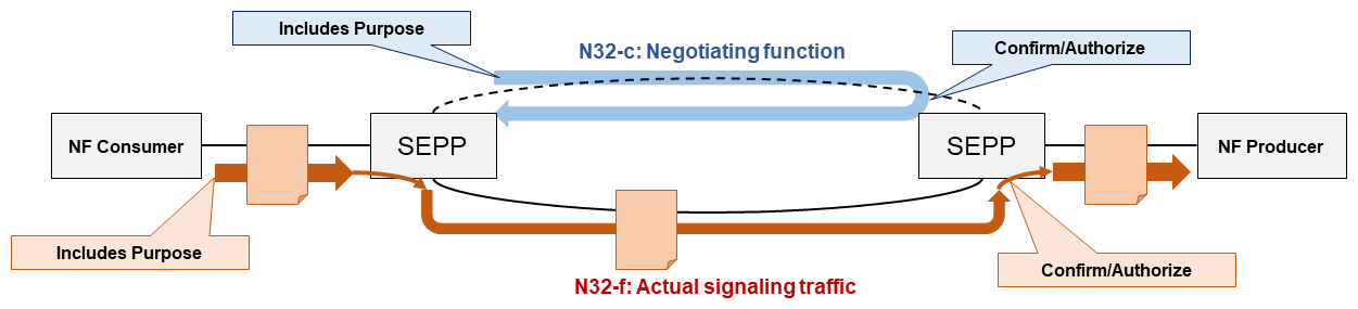
Figure 7 Negotiating use and notifications with added SEPP connection establishment (N32-c) and actual communication (N32-f)
- The function to be used is agreed upon through signaling on the N32-c interface.
- Based on the agreed-upon function, an N32-f interface connection is created to handle the actual message transmission, such as transmitting messages from AMF to UDM.
N32 was initially specified to be used with roaming. For example, N32 would be used as the communication path when a VPLMN NF communicates with an HPLMN NF (or vice versa) so the VPLMN AMF can use the HPLMN UDM service. Then, with the appearance of service-based SMS, use of N32 expanded to include so-called interconnectivity, so that users on different PLMN could send SMS to each other. To enable operators to identify why and how additional N32 interfaces were being used, Rel-17 adds functions to set both the use and objective of creating and using the N32 interface, in both N32-c and N32-f. This enables two network operators to exchange only legitimate messages between their PLMN, based on their contractual relationships, and to reject messages outside of such use.
- S-NSSAI: An identifier for network slices, used by the 5GC.
- Core network: A network comprising switching equipment, subscriber information management equipment, etc. A mobile terminal communicates with the core network via a radio access network.
- MAP: A communication protocol specified by the 3GPP, for managing position registration and other procedures.
- Diameter: A protocol standardized by the Internet Engineering Task Force (IETF), improving on its Remote Authentication Dial In Use (RADIUS) protocol.
- SIP: A call control protocol defined by the Internet Engineering Task Force (IETF) and used for IP telephony with Voice over IP (VoIP), etc.
- API: Interface specification used for exchange between 5GC equipment.
- SMS-IWMSC: An MSC function that receives incoming call short messages from the other party's switch and forwards it to the receiver's Service Center (SC) address.
- SMS-GMSC: An MSC function that receives a short-message transmission from the SC, queries the HLR for the destination, and transmits to the destination switch.
- SEPP: Equipment positioned at the boundary between the 5GC of different operators, to handle control signals.
-
This article has described some of the ...
Open
This article has described some of the functional enhancements added by the 3GPP CT Group in Rel-17. These functions have effects on the Core Network and on UE. The 3GPP CT Group will continue specifying enhancements to 5G systems based on new requirements and NTT DOCOMO will continue contributing to standardization work related to such 5G System enhancements.
-
REFERENCES
Open
- [1] K. Aoyagi et al.: “Overview of 5G Core Network Advanced Technologies in 3GPP Release 16,” NTT DOCOMO Technical Journal, Vol. 22, No. 3, pp.49-61, Jan. 2021.
 https://www.docomo.ne.jp/english/binary/pdf/corporate/technology/rd/technical_journal/bn/vol22_3/vol22_3_006en.pdf (PDF format:1,389KB)
 - [2] 3GPP TS23.122 V17.7.1 - Annex C.4: “Non-Access-Stratum (NAS) functions related to Mobile Station (MS) in idle mode,” Jun. 2022.
- [3] 3GPP TS29.002 V17.2.0: “Mobile Application Part (MAP) specification,” Jun. 2022.
- [4] 3GPP TS29.272 V 17.3.0: “Mobility Management Entity (MME) and Serving GPRS Support Node (SGSN) related interfaces based on Diameter protocol,” Jun. 2022.
- [5] 3GPP TS23.540 V17.0.0: “5G System: Technical realization of Service Based Short Message Service; Stage 2,” Jun. 2022.
- [1] K. Aoyagi et al.: “Overview of 5G Core Network Advanced Technologies in 3GPP Release 16,” NTT DOCOMO Technical Journal, Vol. 22, No. 3, pp.49-61, Jan. 2021.

